Jump to content


Photo

help building extractors


  • Please log in to reply
25 replies to this topic

#1 ACJ

ACJ

    Forum Member

  • Members
  • PipPipPip
  • 197 posts
  • Name:adam
  • Location:south of Perth
  • Car:LH
  • Joined: 26-November 08

Posted 30 June 2011 - 11:48 PM

Hi all

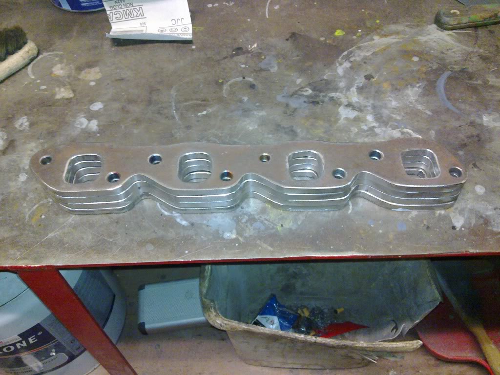
Im in the process of building a set of 4 into 1 extractors with Mega Collectors.

To fit a 355 stroker with VN heads, in a LH. Heads have bigger valves, ported and flowed at 525HP. Cam crane solid F288. I�m hoping to make 500 Hp or just over at about 7000 -7200 RPM.

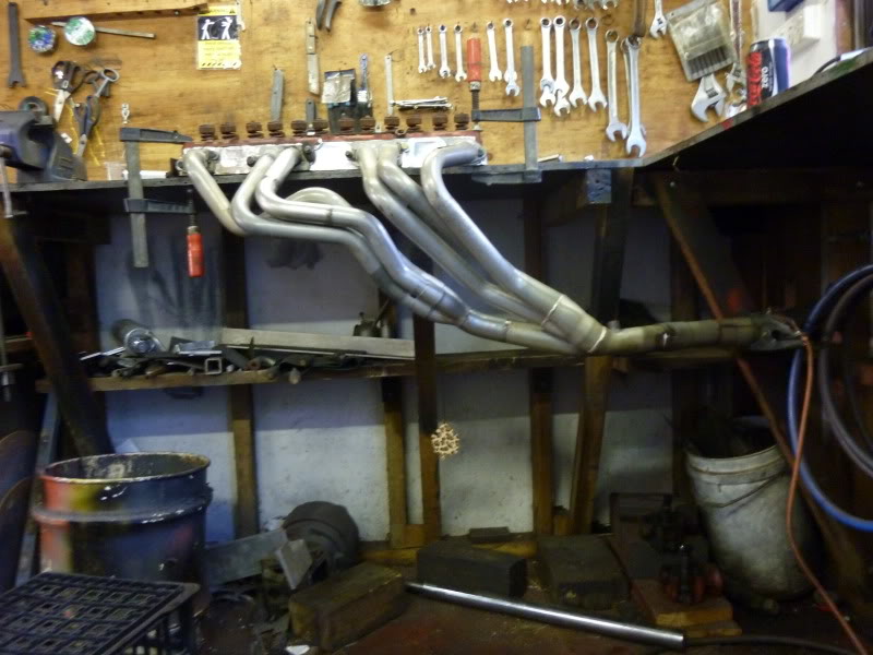
I need some help with the length of the primary pipes and the shape of the collectors.

I think 1 �� primary pipe and the length about 34 or 36 inch would be ok? Is this a good length to give me strong power from 4000 - 4500 and up ?

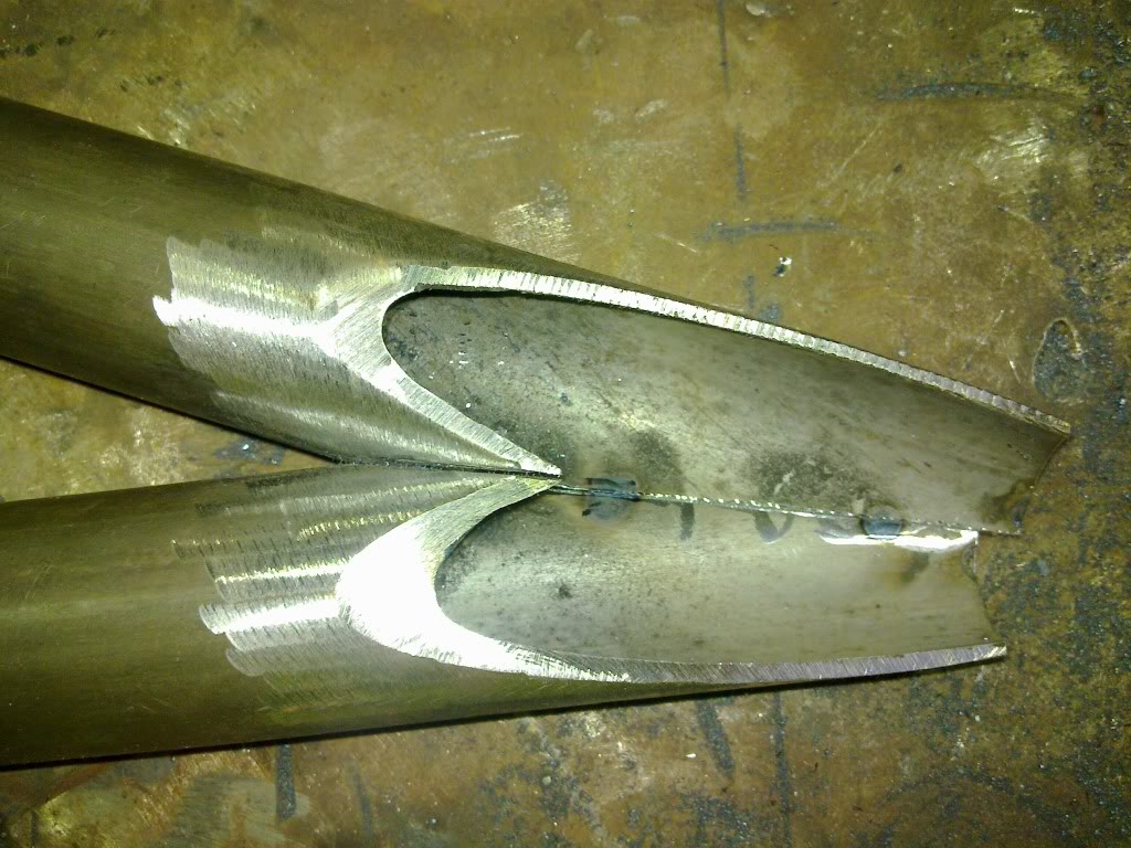
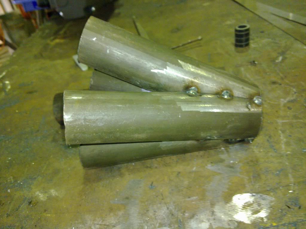
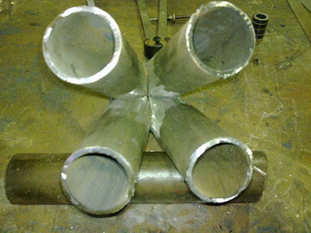
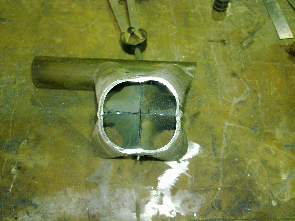
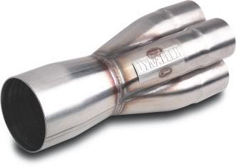
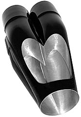
The shape of the collectors seems to be more important these days than the pipes ? The pictures below is what I had in mind. Is the tuned length to the point that all 4 pipes meet or at the end of the collector ?

I think the outlet of the collector should be 2 �� or 2 �� with a 3� transition up to 2 �� ??

All this meeting a single 3� Systems

I would like to keep all sizes as small as possible for this power outcome.

Any thoughts or criticism much appreciated.

Thanks

Posted Image


Posted Image


#2 EunUCh

EunUCh

    Lotsa Posts!

  • Members
  • PipPipPipPipPipPip
  • 2,769 posts
  • Location:not this planet
  • Car:japos
  • Joined: 23-November 06

Posted 02 July 2011 - 08:29 PM

Exhaust systems are bit of science on their own,some very complicated
shit happens in an exhaust because basically you dealing with gasses
at the speed of sound,and it all changes due to temp.revs.etc.
Tuned lenght is just that,remember the days of AM radio,(turn the
dial to the station and it comes on strong but either side it is weak)
I would suggest make prim.pipes as practical as poss. and use the
merge collector.

#3 _oldjohnno_

_oldjohnno_
  • Guests

Posted 02 July 2011 - 09:49 PM

Primary dimensions should be based on rpm range and cam profile. Use PipeMax or one of the online calculators to work it out. The diameter you mentioned sounds about right but the length might be a bit longish..
Merge collectors aren't magic and won't make a big difference over a conventional collector. One thing to look out for is that they add effective length to the primaries so this has to be accounted for. In the early days of merge collectors it was found that in back-to-back testing the merge collectors usually made less power than the conventional type. It wasn't until the primary lengths were adjusted that any gains were seen.

#4 ACJ

ACJ

    Forum Member

  • Members
  • PipPipPip
  • 197 posts
  • Name:adam
  • Location:south of Perth
  • Car:LH
  • Joined: 26-November 08

Posted 03 July 2011 - 11:38 PM

Thanks guys, good information.

This is my understanding in a very simple way

I think the smaller the diameter the better. If it does not restrict the flow at hight RPM. The higher velocity help draw the gas out of other primary pipes.

The lengh of the primary determines the time it takes for the presure waves to go down one primary and back up another one to help scavenge another port ( the longer the pipe the longer time it takes, so it works at a lower RPM and the shorter pipe will get back quicker for higher RPM ) If I get it wrong the extractors will still work but the best gain will not match up with my cam power band as good.

If it is as simple as I think or as complicated as it may be. This just tells me onething. extractors we buy from a shop will only work properly on a motor with the same specifications as the extractors were designed for.

So with as much information as I can get ( I will also Use PipeMax thanks ) I think I have more chance of getting it right or closer than some from a shop. I am thinking of making up small extension ( between the collector and the primary ) just for the dyno and if nesasary I will remake new length primary pipes.

Any more thoughts or criticism much appreciated specialy on the lengh.

Thanks


#5 EunUCh

EunUCh

    Lotsa Posts!

  • Members
  • PipPipPipPipPipPip
  • 2,769 posts
  • Location:not this planet
  • Car:japos
  • Joined: 23-November 06

Posted 05 July 2011 - 08:35 AM

This formula may or may not help for primary pipe lenght
I think its always good to throw around a few ideas before
diving in.
P=(ASD)squared, divided by (1400 x(d squared)
P=primary pipe length in feet
A=exhaust valve opening period in degrees of crank rotation
S=stroke(inches)
D=bore (inches)
d=exhaust valve port diameter(inches)
this formula is supposed to help in determining best wave action in pipe.
The diameter of pipe to use accoding to the source should be slightly larger
than the valve throat diameter as measured below the valve,its all in theory of course but need to start somewhere.

#6 myss427

myss427

    Forum Fixture

  • Members
  • PipPipPipPipPip
  • 1,636 posts
  • Location:Canberra
  • Car:427 hatch, CV8 Monaro, Ve SSV ute. Was part owner A9X sedan until he sold it without telling me!
  • Joined: 17-November 05
Garage View Garage

Posted 05 July 2011 - 08:53 AM

I have built many systems for Toranas, big block 4 into 1's, LS2 into toranas all 4 into 1's and the main problem your going to face is the steering area interfearing with your design. It is going to be almost impossible to maintain an exact copy of side to side designs without altering the steering coloum and crossmemeber for extra room. It can be done if you make extra space like trimming chasis rails, shortening outside of coloum and running Tuff mounts.

#7 _oldjohnno_

_oldjohnno_
  • Guests

Posted 05 July 2011 - 10:07 PM

This formula may or may not help for primary pipe lenght
I think its always good to throw around a few ideas before
diving in.
P=(ASD)squared, divided by (1400 x(d squared)
P=primary pipe length in feet
A=exhaust valve opening period in degrees of crank rotation
S=stroke(inches)
D=bore (inches)
d=exhaust valve port diameter(inches)
this formula is supposed to help in determining best wave action in pipe.
The diameter of pipe to use accoding to the source should be slightly larger
than the valve throat diameter as measured below the valve,its all in theory of course but need to start somewhere.


That formula looks extremely dubious. Either you've inadvertently made a mistake copying it here or it's just a dud. I'd be inclined to just use Blair's formula either directly or via PipeMax.
At any rate I wouldn't stress too much about getting them all exactly the same length, if there was no more than 2 or 3 inches variation I don't think you'll notice the difference. And as the poster above says, just getting the damn things to fit at all can be challenging enough let alone making all the primaries exactly the same.
Sounds like you're on the right track though - a little too small is a lot better than a little too big. Similarly, making the collector overly long won't hurt power as much as making it too short, and it will help broaden the curve. If you like I'll run the numbers through PipeMax later.

#8 rodomo

rodomo

    To advertise here, call 13TORANA

  • Members
  • PipPipPipPipPipPipPip
  • 18,039 posts
  • Name:R - O - B Dammit!
  • Location:Way out west of Melbourne Awstraylya
  • Joined: 10-December 05

Posted 05 July 2011 - 10:44 PM

At any rate I wouldn't stress too much about getting them all exactly the same length, if there was no more than 2 or 3 inches variation I don't think you'll notice the difference.


Is that because a pulse is a pulse? Regardless of where it is in the pipe? I've thought that myself. And over an inch or two, all we're counting is friction?

Next question? Does this hold any merit? Given that the firing order on this bank would be 1-5-3-7? Timing position of primary into collector?

Attached Files


#9 EunUCh

EunUCh

    Lotsa Posts!

  • Members
  • PipPipPipPipPipPip
  • 2,769 posts
  • Location:not this planet
  • Car:japos
  • Joined: 23-November 06

Posted 06 July 2011 - 04:33 PM

Sorry all,thanks oldjohnno for picking that up,my mistake
only the "D" on top line is squared
only the "d" on bottom line is squared
I know we have computers do all this stuff for us now,but for anyone interisted
the book is call"scientific design of exhaust and intake systems".interisting read.

#10 _oldjohnno_

_oldjohnno_
  • Guests

Posted 06 July 2011 - 07:41 PM

Is that because a pulse is a pulse? Regardless of where it is in the pipe? I've thought that myself. And over an inch or two, all we're counting is friction?

Next question? Does this hold any merit? Given that the firing order on this bank would be 1-5-3-7? Timing position of primary into collector?


Let's say the ideal length turns out to be 30", but practicalities force us to make one or two at 28-1/2" and one or two 31-1/2" long.
Let's also say our engine has a torque peak of 6000rpm. The odd lengthed tubes are now going to be at their best at roughly 300rpm above or below our design speed of 6000. Does it matter? I don't think so, at least not with a relatively mild engine like the OP's 500hp 355. There won't be much drop in torque 300rpm above or below the peak so really all that's happened is the peak hp might be down a tiny amount and the spread of torque will be a tiny amount broader. For a very highly tuned engine (eg 2hp/cu.in or more) with a very pronounced peak it would be different but in this case I wouldn't worry.

I don't know about the idea of setting the primaries in sequence around the collector, I've never tried it. I know a lot of people do it though, and a lot of people think they should be sequenced diagonally instead. As far as I know no-one has proven any conclusive gains. My gut feeling is that there would be so much turbulence in the collector entry that the engine wouldn't care which way they were sequenced. So basically I'd just stick them where it was easy (or at least possible) to fit them in.

Philip Smiths work was interesting, but I think even the current edition is mainly useful as a historical piece. For a long time now, nearly all the higher level design work has been based on the work of Gordon Blair. If it's good enough for the ProStock and the F1 guys it's good enough for me..

Edited by oldjohnno, 06 July 2011 - 07:42 PM.


#11 ACJ

ACJ

    Forum Member

  • Members
  • PipPipPip
  • 197 posts
  • Name:adam
  • Location:south of Perth
  • Car:LH
  • Joined: 26-November 08

Posted 06 July 2011 - 09:08 PM

Thanks, more good information

I had a go at this formula with a good outcome of 33.57 incher.

But the cam degrees was advertised (296) not @ 50�(260). Valve throat diameter of 1.4�. As the valves are 1.6� and the inside edge of the seat was 1.45 so I had a guess at 1.4� for the throat diameter.


Yes, I would appreciate if you could run my numbers through PipeMax


Seems to be a lot of variables and critical darter to make these formula work accurately ? I still think if I make a very simple set of extractors with 30 inch primary and 8 x 2 inch long and 8 x 4 inch long extension pipes to slip on the end of the primary befor the collectors when it�s on the dyno may be the best result ?

Some fianger I made.

Posted Image


#12 warrenm

warrenm

    Forum Fixture

  • Members
  • PipPipPipPipPip
  • 2,118 posts
  • Location:Central West NSW
  • Car:1972 LJ Torana
  • Joined: 08-November 05
Garage View Garage

Posted 07 July 2011 - 08:44 AM

I've used the formulas from the book "Scientific design of exhaust and intake systems" then used Pipmax, the pipe lengths were 1/4" different using the same info.
oldjohnno, What can you direct me to some of Gordon Blair's work please,books etc.

Edited by warrenm, 07 July 2011 - 08:50 AM.


#13 _Drag lc_

_Drag lc_
  • Guests

Posted 07 July 2011 - 08:11 PM

when i was mucking around with n/a 202s i brought some proper burns stainless merge collectors and fitted them to my headers unsure if there was any gain as it was also fitted with a moroso vac pump aswell but due to some slight issues with the head never really did go better at the track. :mellow:


heres a pic of one collector fitted.

Posted Image

#14 _Mistagear_

_Mistagear_
  • Guests

Posted 07 July 2011 - 08:25 PM

I've used the formulas from the book "Scientific design of exhaust and intake systems" then used Pipmax, the pipe lengths were 1/4" different using the same info.
oldjohnno, What can you direct me to some of Gordon Blair's work please,books etc.


I fooled around back in the Gp C days with Anti Reversion Exhaust systems on L34s, we found with trial and error on the dyno we were able to make greater HP over a broader range using this type of exhaust. If I were building a custom set of headers, I would explore this option and truly believe the improved volumetric efficiency gives greater gains than perfectly equal primaries
I do not have any surviving records from those days to help, but from memory, we found 30"/32" primaries gave a good balance between top-end to mid-range. Placing a bend in the pipe very close to the anti-reversion lip/sleeve assists with preventing exhausted gas from sucking back into the chamber.
We even built an exhaust which turned upwards and over the tappet covers, crossed over the other side of the engine and exited on the opposite side of each cylinder head. The angle the gasses exited the port was improved and this system made the best HP but was a plumbing nightmare under the bonnet and a total pig to work on any other part of the engine when installed that we only ever ran it at one meeting.
Just thinking aloud, sorry for interrupting your discussion, good memories and fun to tell other people who may realise just how difficult and crazy playing around with cars can become.
Cheers, M

#15 _oldjohnno_

_oldjohnno_
  • Guests

Posted 07 July 2011 - 09:07 PM

I've used the formulas from the book "Scientific design of exhaust and intake systems" then used Pipmax, the pipe lengths were 1/4" different using the same info.
oldjohnno, What can you direct me to some of Gordon Blair's work please,books etc.


Amazon Link

His simulation software is also said to be very very good, but it's a bit expensive for casual use (several thousand UK pounds for both packages last time I looked) and besides I think it would require a bit more commitment than an amateur like me is prepared to give. Unfortunately he died a few months ago and I don't know if anyone else will be maintaining the software. He also published a few SAE papers and quite a few fairly in-depth articles in Race Engine Technology magazine. He also did a huge amount of work with two-strokes and wrote about them too, and that's how I first discovered him.

I'm a bit surprised Smith's result matched so closely - his method may be deserving of a lot more credit than I gave it...

#16 warrenm

warrenm

    Forum Fixture

  • Members
  • PipPipPipPipPip
  • 2,118 posts
  • Location:Central West NSW
  • Car:1972 LJ Torana
  • Joined: 08-November 05
Garage View Garage

Posted 08 July 2011 - 09:21 AM

These are the headers that I made using Pipemax, I picked up 3/10 sec on the 1/8th mile going from Genie headers to these.

Attached Files


#17 ACJ

ACJ

    Forum Member

  • Members
  • PipPipPip
  • 197 posts
  • Name:adam
  • Location:south of Perth
  • Car:LH
  • Joined: 26-November 08

Posted 08 July 2011 - 11:35 AM

Hi Warrenm

Your extractors look good to me. The primary must be about the same lengh and nice flowing bends. The angel that the primary meat together is shalow. All this together I think help, 3/10 off your time card is very good.

Did you sand bend your primary pipe ?

To oldjohnno

Thanks for lots of good information (and eveyone). Do you know the RPM per inch of primary pipe eg If my pipes are out 1000 rev would you cut off 1 inch or 5 inchers ?

All in all I think Mistagear hit the nail on the head �Just thinking aloud, sorry for interrupting your discussion, good memories and fun to tell other people who may realise just how difficult and crazy playing around with cars can become� Love it

Thanks


#18 warrenm

warrenm

    Forum Fixture

  • Members
  • PipPipPipPipPip
  • 2,118 posts
  • Location:Central West NSW
  • Car:1972 LJ Torana
  • Joined: 08-November 05
Garage View Garage

Posted 09 July 2011 - 08:31 AM

I cut & welded mandrel bends. I pulled the last few remaining strands of hair from my head building them.

#19 _oldjohnno_

_oldjohnno_
  • Guests

Posted 09 July 2011 - 08:02 PM

I cut & welded mandrel bends. I pulled the last few remaining strands of hair from my head building them.


The bald look is in, you're a trendsetter. And seeing as you've got no more left to lose I reckon you should build a set or two for me ^_^

#20 _oldjohnno_

_oldjohnno_
  • Guests

Posted 09 July 2011 - 09:03 PM

ACJ, this is what pipemax had to say. I had to make a couple of assumptions about your engine but this should be very close for a target of 500hp at around 7200:

Primary dia - 1.76" to 1.88"

Pri. length - 28.7" to 31.1"

Collector dia - 3.48"

Collector length - 16"

For tapered collector use 3" x 3.5" x 16"

Use a H pipe 16" from end of primaries ie. at end of collector if you'll be using mufflers.

A very rough rule of thumb at this rev range would be around 3-1/2" per 1000rpm. I know I mentioned this before but I'll say it again anyway - I wouldn't stress too much about merge collectors. I know they are currently fashionable and can make a little bit more if you get them right but they also seem to be able to cost power if they aren't 100%. Conventionals seem to be more forgiving.

#21 ACJ

ACJ

    Forum Member

  • Members
  • PipPipPip
  • 197 posts
  • Name:adam
  • Location:south of Perth
  • Car:LH
  • Joined: 26-November 08

Posted 10 July 2011 - 12:38 PM

Thanks very much for running pipemax.

I have 3 different lenghs from 29 to 33 incher. So if 3 � incher is about a 1000 rpm and I made my starting point 31 inches I should only be about 500 rev out. This would be a very good starting point.

I have a question about the collectors as I will be running a full exhaust and muffler.

If the collector and tapered collector are 3 � inch dia at the out let, Do I put a reverse cone back to 2 � or 3 inch and then continue the exhaust pipe. If not what determines the end lengh of the collectors ?

Thanks


#22 _oldjohnno_

_oldjohnno_
  • Guests

Posted 10 July 2011 - 09:57 PM

The length is measured to wherever there is a sudden change in cross-sectional area or volume. That's why you'd put a big H pipe (or a termination box like a big empty muffler) right at the end of the collector. Otherwise the exhaust system just looks like more collector length as far as the engine is concerned. Don't use a reverse cone or reducer - it'll reflect a positive wave back which is the opposite of what you want.

#23 ACJ

ACJ

    Forum Member

  • Members
  • PipPipPip
  • 197 posts
  • Name:adam
  • Location:south of Perth
  • Car:LH
  • Joined: 26-November 08

Posted 16 July 2011 - 09:18 PM

I would like to thank everyone for all the help and good information.

I started playing around and made some flanges and collectors (just out of old pipe for a test ) so far so good

Mite continue this post in fabrication now thanks all.


Posted Image

Posted Image

Posted Image

Posted Image

Posted Image


#24 _Liam_

_Liam_
  • Guests

Posted 16 July 2011 - 11:15 PM

Make sure you leave a bit of material on those pipes to form a Goilet. Apparently it will increase flow more efficiently.

#25 ACJ

ACJ

    Forum Member

  • Members
  • PipPipPip
  • 197 posts
  • Name:adam
  • Location:south of Perth
  • Car:LH
  • Joined: 26-November 08

Posted 17 July 2011 - 12:16 AM

The inside point is the length of the goilet.This is with a convergent angle of 12 degree.But this is just a test pipe wich is smaller in diameter so the larger pipe will be longer still.

Thanks

Posted Image


1 user(s) are reading this topic

0 members, 1 guests, 0 anonymous users