Article description: Thanks to Flamenco (Sean) for the info!
Category: General LH-LX-UC
Date added: Aug 11 2008, 07:03 PM
Article starter: Joshua
The individual '4 in one' gauges on the right hand side of the SL/R dash are all the same and also interchangeable... The SL/R dash uses different senders to the normal SL dash (with the warning lights) and the senders need swapping with the correct type in order to function.
When one (or all) of these fail it is usually because of one of the following:
Gauges all read full/max - The voltage regulator is damaged, sender wire/s are shorted against the chassis or there is a bad earth to the cluster...
One gauge doesn't function - Sender for the gauge is damaged or the wire is broken, not connected.
One gauge reads incorrectly - Incorrect sender fitted or gauge damaged.
The '4 in 1' gauges actually consist of two main halves or units (see below).
Each needle is a separate gauge - a standard SL fuel gauge can be substituted for a gauge deemed inoperative. The SL fuel gauge is what I will be using as a replacement for one of the faulty SL/R gauges in this guide. You can use the same guidelines below using an old SL/R cluster if you have one spare!https://cache.gmh-to...ana/3gauges.jpg
First we need to determine if the guage is at fault - if all the sender wiring looks to be in place on the engine then we can move onto the gauge cluster...
1) Remove the guage cluster from the LH/LX.
2) On the back of the '4 in 1' gauges there are eight terminals with brass nuts & washers - these are the positive and negative terminals of the four gauges (two terminals per gauge).
3) With a 9volt battery, probe the pairs of terminals (very briefly - only a couple of seconds or so). If the gauge moves when power is applied to the terminals it's fine.
4) If one or more gauges didn't respond when power was applied, read on...
5) Remove the 'window' part of the gauge cluster.
6) Undo and set aside the eight nuts and washers for the '4 in 1' gauges.
7) Undo the centre screw which holds the black plastic logo square for the gauges.
8) Remove the logo square and the two halves of the gauges from the rest of the cluster.
9) If only one half of the gauges is affected you need only remove the metal plate (with the scales) from that half.
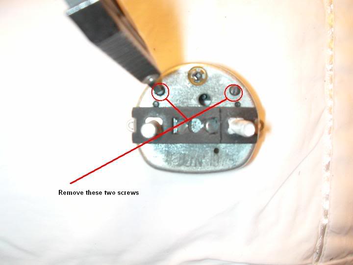
10) I'll now start dismantling the SL fuel gauge I'm using as a replacement - remove the two screws underneath it. (See below)
11) You can then remove the triangular part on the other side - no need to remove the needle first, it will stay attached to the steel rod it's mounted to.
12) The needle and pole should fall out if you tip the gauge upside down.
13) Scrape away the 'glue' that the guage's wires are held onto the terminals with - use a stanley knife or a flat blade screwdriver (be careful not to damage the gauge!)
14) This part must be done with care: There is a brass disc holding the gauge to the housing, this can be removed with some small locking pliers or a similar tool...
Grip the brass disc and twist it slowly until it pops out of the housing (The disc is pressed in, there is no thread). (See Below)https://cache.gmh-to...brasscircle.jpg
15) Once the brass disc is removed the gauge can be removed from the SL fuel gauge housing.
16) Draw a pen line around the faulty SL/R guage to aid repositioning with the replacement gauge. Repeat steps 10 to 14 on the faulty gauge from the SL/R cluster.
17) Place the replacement gauge within the pen line you just drew on the SL/R cluster. Put some araldyte or superglue on the brass disc and pop it lightly back into place.
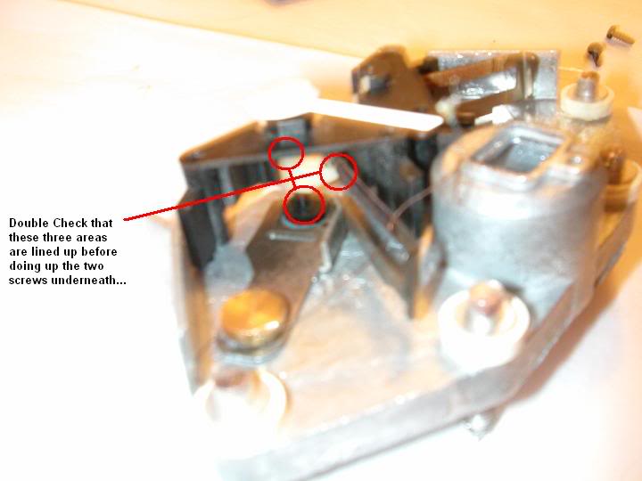
18) This is a bit fiddly, put the 'needle and pole' back into the circular plastic holder and carefully line the slot up with the side of the gauge.
19) Carefully position the triangular plastic piece over the 'needle & pole', Once in place, you can hold it while you put the two self tappers into the back of the housing. (See Below)
20) Now we need to solder the two wires back onto the terminals that we scraped the glue from before... Make sure they are the right polarity! Check one of the existing gauges for a reference if unsure - one of the thin wires runs straight down the middle of the bimetal strip of the gauge, the other thin wire is coiled around the bimetal strip. (See Below)https://cache.gmh-to...a/soldering.jpg
21) Test the replacement gauge works by using the 9volt battery again.
22) All being well refit the scale plate back onto the gauges and reinstall the gauges back into the cluster... Job done! - (Flamenco)
VIEW ARTICLE
Repairing An Sl/r Dash Cluster


