


Yep, one more UC with a SBC project !!!
Started by
Struggler
, Mar 25 2009 04:28 PM
476 replies to this topic
#201
 _355 EH_
_355 EH_
-

- Guests
Posted 27 March 2011 - 12:57 AM
anymore news on the beast stuggler? ive enjoyed this thread so far
#202
Struggler
-
- Members
-

- 2,426 posts
Forum Fixture
- Name:Andrew or AJ
- Location:Canberra A.C.T.
- Car:UC Sedan
- Joined: 08-November 05
Posted 27 March 2011 - 12:43 PM
Hi Paul, haven't done a whole lot recently, been tied up with other stuff but hope to have a good run at it in the next couple of weeks.
I will do a bit of an update in the next couple of days, hang in there !!
I will do a bit of an update in the next couple of days, hang in there !!
#204
Struggler
-
- Members
-
- 2,426 posts
Forum Fixture
- Name:Andrew or AJ
- Location:Canberra A.C.T.
- Car:UC Sedan
- Joined: 08-November 05
Posted 13 April 2011 - 03:55 PM
I haven't done a great deal to the car lately, busy with other stuff.
About 2 months ago I got it over to a motor trimmer mate and got him to make a headlining out of some marine carpet type stuff. Sounds dodgy I know but it turned out really well. He did the A,B and C pillars as well as covering a new parcel shelf I made.
 P1020263.JPG 132.93K
4 downloads
P1020263.JPG 132.93K
4 downloads
The car then sat around for a while before I started to drag the dash and wiring out of the roof space and tackled it. I changed the gauges as I wasn't happy with the Sport Comp mechanicals and went with some electric Ultra Lites.
P1020262.JPG 71.72K
3 downloads
I ended up ripping the whole wiring loom apart and cutting out a few circuits as well as tidying up a lot of stuff. The engine bay wiring has been totally revised (headlights etc run down the outside of the drivers inner guard, some wiring is in the chassis rails and the coil is now inside the car).
P1020261.JPG 144.56K
4 downloads
P1020265.JPG 119.59K
4 downloads
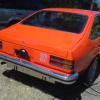
Here is a pic of how the car stood this morning (for some reason I cannot get the colour right, regardless of sunlight/flash etc it always looks too bright or way washed out).
P1020266.JPG 60.49K
3 downloads
I am still going on the wiring (need to run the battery lead from the boot forward and tidy up some other stuff)but am nearly ready to build an engine for it. I had a grand plan of building a 327 with the low blower pictured previously in the thread but sold it off to a mate recently and am now a bit lost as to what to do. I will probably slap together a 350 to get it going but will keep you all posted. I really want to fit the running gear and get it all sorted before continuing on with the bodywork.
Let me know what you reckon ! Thanks.
About 2 months ago I got it over to a motor trimmer mate and got him to make a headlining out of some marine carpet type stuff. Sounds dodgy I know but it turned out really well. He did the A,B and C pillars as well as covering a new parcel shelf I made.
P1020263.JPG 132.93K
4 downloadsThe car then sat around for a while before I started to drag the dash and wiring out of the roof space and tackled it. I changed the gauges as I wasn't happy with the Sport Comp mechanicals and went with some electric Ultra Lites.
P1020262.JPG 71.72K
3 downloadsI ended up ripping the whole wiring loom apart and cutting out a few circuits as well as tidying up a lot of stuff. The engine bay wiring has been totally revised (headlights etc run down the outside of the drivers inner guard, some wiring is in the chassis rails and the coil is now inside the car).
P1020261.JPG 144.56K
4 downloads
P1020265.JPG 119.59K
4 downloadsHere is a pic of how the car stood this morning (for some reason I cannot get the colour right, regardless of sunlight/flash etc it always looks too bright or way washed out).
P1020266.JPG 60.49K
3 downloadsI am still going on the wiring (need to run the battery lead from the boot forward and tidy up some other stuff)but am nearly ready to build an engine for it. I had a grand plan of building a 327 with the low blower pictured previously in the thread but sold it off to a mate recently and am now a bit lost as to what to do. I will probably slap together a 350 to get it going but will keep you all posted. I really want to fit the running gear and get it all sorted before continuing on with the bodywork.
Let me know what you reckon ! Thanks.
#205
_dirtbag_
_dirtbag_
-
- Guests
Posted 13 April 2011 - 04:53 PM
Looks awesome Andrew. A lot better than the old silver Centura you used to burn around in during the old Horsepower Haven days : ) Went hard though from memory. Good old 265 
#206
_LJ355_
_LJ355_
-
- Guests
Posted 13 April 2011 - 08:07 PM
looks great its coming together nicely be good to see at the track soon 
#207
Struggler
-
- Members
-
- 2,426 posts
Forum Fixture
- Name:Andrew or AJ
- Location:Canberra A.C.T.
- Car:UC Sedan
- Joined: 08-November 05
Posted 13 April 2011 - 09:06 PM
Looks awesome Andrew. A lot better than the old silver Centura you used to burn around in during the old Horsepower Haven days : ) Went hard though from memory. Good old 265
Thanks mate, they were the days !! That car was a lot of fun, upset quite a few people. The 265 was actually about 277 and used 308 flat top pistons !
looks great its coming together nicely be good to see at the track soon
Thanks Lee, I'm getting there slowly, life keeps getting in the way.
#208
_355 EH_
_355 EH_
-
- Guests
Posted 15 April 2011 - 01:07 AM
its lookin killar Andrew, i like the colour, ive just bought a VB commodore as a budget drag car im thinking a bright green also.
#209
Struggler
-
- Members
-
- 2,426 posts
Forum Fixture
- Name:Andrew or AJ
- Location:Canberra A.C.T.
- Car:UC Sedan
- Joined: 08-November 05
Posted 26 April 2011 - 08:23 PM
its lookin killar Andrew, i like the colour, ive just bought a VB commodore as a budget drag car im thinking a bright green also.
Thanks Paul, the colour is a real attention grabber, the motor trimmer got sick of passers-by asking what colour the car was !
#210
Struggler
-
- Members
-
- 2,426 posts
Forum Fixture
- Name:Andrew or AJ
- Location:Canberra A.C.T.
- Car:UC Sedan
- Joined: 08-November 05
Posted 26 April 2011 - 08:29 PM
On another note I think I have the engine choice sussed out.
I spent last Saturday driving down to Berwick in Melbourne and back. Picked up a 400 SBC block with aftermarket splayed caps, steel crank, good rods and SRP pistons. Got a great deal from a racer that upgraded mid engine build. Everything is brand new, just needs all the usual detail work and putting together. Having said that though there is a lot of work in clearancing blocks, getting rods to clear camshafts and pistons to clear valves. I may get a few pics and post them up tomorrow.
I spent last Saturday driving down to Berwick in Melbourne and back. Picked up a 400 SBC block with aftermarket splayed caps, steel crank, good rods and SRP pistons. Got a great deal from a racer that upgraded mid engine build. Everything is brand new, just needs all the usual detail work and putting together. Having said that though there is a lot of work in clearancing blocks, getting rods to clear camshafts and pistons to clear valves. I may get a few pics and post them up tomorrow.
#211
Struggler
-
- Members
-
- 2,426 posts
Forum Fixture
- Name:Andrew or AJ
- Location:Canberra A.C.T.
- Car:UC Sedan
- Joined: 08-November 05
Posted 17 May 2011 - 11:38 AM
I have been pretty busy getting this block sorted out. As I said earlier I purchased it second hand off a racer that upgraded. The block had been line honed (through the mains tunnel ) as it had aftermarket caps fitted. It had also been decked and initially appeared to have been bored and honed. A sonic test had also been performed and this was the real clincher, it had good bore thickness everywhere. Here is a pic as it sat when I got it home.
IMG_7886.jpeg 54.75K
2 downloads
It also came with a brand new (in the box marked "made in China") COME steel crank that looked flash but upon close inspection had a couple of spots where despite being machined it still had untouched metal (about 6mm in diameter).
IMG_7722.jpeg 49.73K
3 downloads
Also included was a set of Eagle H beam rods and a set of SRP flat top pistons. The whole lot had been balanced and looked ready to go. I knew there would be clearance issues so started on a dummy assemble to see where we were at. The pan rails and both sides of the bore needed grinding to clear the big rods (similar to what is needed for a 355 308).
P1020303.JPG 124.21K
2 downloads
Once I got all this to clear I pulled it apart and did the usual block work such as enlarging and radiusing a few oil galleries and knocking off the sharp edges. The block had already had a few oil galleries tapped for screw in plugs so this saved me some work. The oil drains at the rear of the valley got opened up a bit as well and the holes in the middle had already been drilled and tapped (apparently the machine work had all been done by John Sidney in Clayton who has a fairly good rep.). The block looked like it had been previously cleaned with some sort of blasting medium as it had a good amount of rust on the non machined areas. Someone had also tried to polish the valley in the past and it was impossible to clean it all up so I just painted the block inside and out after a good clean. It then got a fresh set of cam bearings belted into it.
P1020301.JPG 111.14K
1 downloads
P1020300.JPG 113.83K
1 downloads
Back together it went again, this time to check rod to cam clearances and piston to valve. The cam I will be using is a good size solid roller, pretty much what most serious guys run in a street/strip type application. I have had this cam and lifters lying around for a few years and never got around to using them (was having too much fun with the solid cam combo !).
P1020306.JPG 88.13K
1 downloads
P1020313.JPG 56.17K
1 downloads
Anyway it has a heap of lift and on 3.75" stroke motors often the cam lobes will hit the rods as they go past each other. In this case the rods had at least 0.060" to spare so I didn't need to grind any off the shoulders. Next I had to fit a head with some weak springs (I use the springs that hold the door trim against the window winder in a Holden), degree in the cam and check for piston to valve clearance. The problem area here is just either side of TDC on the overlap. The heads I am using are an old set of Bowties that were ported years ago. Again I have had them lying around for years and never got to fit them to anything. They have been decked heaps and the intake valve is proud of the deck about 0.060" already ! I took this opportunity to measure up for pushrod length and check rocker geometry. As luck would have it the pushrods I was using are too long and a pushrod the right length hits the head. More clearancing required ! Once I got that sorted out I could continue with the piston to valve check. The deal here is to turn the engine over very slowly and stop every 2 or 3 degrees (in a range from about 20 deg BTDC to 20 ATDC) and check to see how much room there is by pushing down on the weak spring until the valve contacts the piston. With no head gasket the intake valve had about 0.055" to go before things got nasty however the exhaust valve hit so bad there was about a 25 degree window where I couldn't turn the engine around. I ended up giving the valve more and more lash until the engine would turn over. Long story short I need some serious flycutting on the exhaust relief. Off came the head again and I pulled all the valves out and made a centre punch out of an old valve. I set the engine at 8 degrees BTDC as this was about the point of maximum interference and slid my valve stem centre punch down the exhaust valve guide and punched a mark into the top of the piston. This then gives me the centre of the flycut required to clear the valve. I checked the valve angle as opposed to the head face (in this case 23 degrees), packed them up and posted them off to Special Piston Services in Dandenong to get the new reliefs cut. Back apart came the engine again for yet another clean, ready to be assembled for, hopefully, the last time. Here is a pic of the piston before machining.
IMG_9808.jpeg 27.28K
1 downloads
While the pistons are away I still kept busy by checking and adjusting the crank end float (which involved carefully sanding down the thrust face of the bearings) and getting the balancer bore honed out to suit the crank snout. Both these areas can be a problem with aftermarket cranks, the machine work required is only tenths of a thousanth of an inch but it can be enough to be a problem. There is nothing worse than struggling to get a balancer on and off the engine when it has too much interference fit.
Another trap is the rear main seal. A 400 has a bigger seal area on the crank than smaller SBC's and therefore uses a different seal. Due to the larger diameter, the seal area of the block ends up getting machined when the main tunnel gets bored. This nececitates a special RMS for align bored 400's. It can be tricky to find so I have ordered a couple from the US and are still waiting for them to arrive.
I have just given the block its final once over and fitted the oil gallery plugs, welsh plugs and camshaft. For the welsh plugs I have a machined up chunk of aluminium that I use. It has a locating snout and a step that uses the top of the plug to push them in. It does a great job and doesn't mark the plug like a socket does. The other machined diameters are to allow me to knock out SBC and 308 cam bearings. You can see it sitting on the block in this pic.
P1020312.JPG 86.79K
2 downloads
As another point of interest there is a small plug that lives under the rear main cap. This plug is often forgotten when getting the block cleaned and also forgotten upon reassembly. I tap out the gallery and use a screw in plug that you can just see down the hole on the left. If you leave this plug out it doesn't affect oil pressure at all but allows oil to bypass the filter. Not good for anyone ! In this pic you can also see the machined down RMS locating lip.
P1020310.JPG 66.16K
2 downloads
Thats enough engine porn for now. I'll post a few more pics once the rear main seal and pistons show up.
I hope the pics and commentary aren't too boring !!
IMG_7886.jpeg 54.75K
2 downloadsIt also came with a brand new (in the box marked "made in China") COME steel crank that looked flash but upon close inspection had a couple of spots where despite being machined it still had untouched metal (about 6mm in diameter).
IMG_7722.jpeg 49.73K
3 downloadsAlso included was a set of Eagle H beam rods and a set of SRP flat top pistons. The whole lot had been balanced and looked ready to go. I knew there would be clearance issues so started on a dummy assemble to see where we were at. The pan rails and both sides of the bore needed grinding to clear the big rods (similar to what is needed for a 355 308).
P1020303.JPG 124.21K
2 downloadsOnce I got all this to clear I pulled it apart and did the usual block work such as enlarging and radiusing a few oil galleries and knocking off the sharp edges. The block had already had a few oil galleries tapped for screw in plugs so this saved me some work. The oil drains at the rear of the valley got opened up a bit as well and the holes in the middle had already been drilled and tapped (apparently the machine work had all been done by John Sidney in Clayton who has a fairly good rep.). The block looked like it had been previously cleaned with some sort of blasting medium as it had a good amount of rust on the non machined areas. Someone had also tried to polish the valley in the past and it was impossible to clean it all up so I just painted the block inside and out after a good clean. It then got a fresh set of cam bearings belted into it.
P1020301.JPG 111.14K
1 downloads
P1020300.JPG 113.83K
1 downloadsBack together it went again, this time to check rod to cam clearances and piston to valve. The cam I will be using is a good size solid roller, pretty much what most serious guys run in a street/strip type application. I have had this cam and lifters lying around for a few years and never got around to using them (was having too much fun with the solid cam combo !).
P1020306.JPG 88.13K
1 downloads
P1020313.JPG 56.17K
1 downloadsAnyway it has a heap of lift and on 3.75" stroke motors often the cam lobes will hit the rods as they go past each other. In this case the rods had at least 0.060" to spare so I didn't need to grind any off the shoulders. Next I had to fit a head with some weak springs (I use the springs that hold the door trim against the window winder in a Holden), degree in the cam and check for piston to valve clearance. The problem area here is just either side of TDC on the overlap. The heads I am using are an old set of Bowties that were ported years ago. Again I have had them lying around for years and never got to fit them to anything. They have been decked heaps and the intake valve is proud of the deck about 0.060" already ! I took this opportunity to measure up for pushrod length and check rocker geometry. As luck would have it the pushrods I was using are too long and a pushrod the right length hits the head. More clearancing required ! Once I got that sorted out I could continue with the piston to valve check. The deal here is to turn the engine over very slowly and stop every 2 or 3 degrees (in a range from about 20 deg BTDC to 20 ATDC) and check to see how much room there is by pushing down on the weak spring until the valve contacts the piston. With no head gasket the intake valve had about 0.055" to go before things got nasty however the exhaust valve hit so bad there was about a 25 degree window where I couldn't turn the engine around. I ended up giving the valve more and more lash until the engine would turn over. Long story short I need some serious flycutting on the exhaust relief. Off came the head again and I pulled all the valves out and made a centre punch out of an old valve. I set the engine at 8 degrees BTDC as this was about the point of maximum interference and slid my valve stem centre punch down the exhaust valve guide and punched a mark into the top of the piston. This then gives me the centre of the flycut required to clear the valve. I checked the valve angle as opposed to the head face (in this case 23 degrees), packed them up and posted them off to Special Piston Services in Dandenong to get the new reliefs cut. Back apart came the engine again for yet another clean, ready to be assembled for, hopefully, the last time. Here is a pic of the piston before machining.
IMG_9808.jpeg 27.28K
1 downloadsWhile the pistons are away I still kept busy by checking and adjusting the crank end float (which involved carefully sanding down the thrust face of the bearings) and getting the balancer bore honed out to suit the crank snout. Both these areas can be a problem with aftermarket cranks, the machine work required is only tenths of a thousanth of an inch but it can be enough to be a problem. There is nothing worse than struggling to get a balancer on and off the engine when it has too much interference fit.
Another trap is the rear main seal. A 400 has a bigger seal area on the crank than smaller SBC's and therefore uses a different seal. Due to the larger diameter, the seal area of the block ends up getting machined when the main tunnel gets bored. This nececitates a special RMS for align bored 400's. It can be tricky to find so I have ordered a couple from the US and are still waiting for them to arrive.
I have just given the block its final once over and fitted the oil gallery plugs, welsh plugs and camshaft. For the welsh plugs I have a machined up chunk of aluminium that I use. It has a locating snout and a step that uses the top of the plug to push them in. It does a great job and doesn't mark the plug like a socket does. The other machined diameters are to allow me to knock out SBC and 308 cam bearings. You can see it sitting on the block in this pic.
P1020312.JPG 86.79K
2 downloadsAs another point of interest there is a small plug that lives under the rear main cap. This plug is often forgotten when getting the block cleaned and also forgotten upon reassembly. I tap out the gallery and use a screw in plug that you can just see down the hole on the left. If you leave this plug out it doesn't affect oil pressure at all but allows oil to bypass the filter. Not good for anyone ! In this pic you can also see the machined down RMS locating lip.
P1020310.JPG 66.16K
2 downloadsThats enough engine porn for now. I'll post a few more pics once the rear main seal and pistons show up.
I hope the pics and commentary aren't too boring !!
#212
_LJ355_
_LJ355_
-
- Guests
Posted 17 May 2011 - 07:29 PM
sounds like is going to be a tuff motor mate is that a special paint you have used ?
and love the detailed info very interesting
and love the detailed info very interesting
#213
lxsstorana
-

- Members
-
- 2,499 posts
Forum Fixture
- Name:Mick
- Location:Eastwood, Sydney
- Car:SS Hatchback
- Joined: 23-March 06
Posted 17 May 2011 - 07:42 PM
I hope the pics and commentary aren't too boring !!
This is a great thread with alot of information, which is great for us mere mortal members (who can't do the stuff you can).
Keep it coming.

Cheers Mick.
#215
TerrA LX
-

- Members
-
- 14,241 posts
Fulcrum Fixture
- Location:Sid 'n' knee
- Joined: 31-May 06
Posted 18 May 2011 - 12:00 AM
Hey awesome work as usual. May I ask what paint you used and what sort of interference you shoot for on the snout to balancer?
#216
Struggler
-
- Members
-
- 2,426 posts
Forum Fixture
- Name:Andrew or AJ
- Location:Canberra A.C.T.
- Car:UC Sedan
- Joined: 08-November 05
Posted 18 May 2011 - 10:07 AM
Hi guys, thanks for all the positive comments.
The paint is just your regular Wattyl Kill Rust epoxy enamel (the colour is Pewter, same as the roll cage and other painted fittings). Lately I have been brushing it on lightly as this pushes it right into all the pores of the casting. I have been using it for years on the outside of engines but this is the first time I have painted the insides. I have been trialling a small patch of it in the valley of another engine and it seems to have stood up well so far so I'll see how this one goes. I did go with the most conspicious colour I had here so it would stick out in the filter if some came unstuck (I have an oil filter cutter so I can make regular inspections). I must say that even at this stage it has been handy. When cleaning the block for the last time it was really easy to see everything in the valley and oil does run off it quickly, rather than partially soaking into the cast iron. Also being a bright colour external oil leaks can be easily detected and traced.
The balancer snout should be about a 0.001" interference (on a snout that is SBC/308 size). The ATI instruction sheet says between 0.0012" and 0.0008". As the snout gets larger in diameter the interference needs to be greater so a BBC would need to be tighter. I ended up at about 0.0009". It is easy to hone on the same machine used to do rod big and small ends and only took a few minutes to take just over half a thou out of it.
I was only going to slap together another short stroke engine on the cheap for a bit of fun but ultimately decided that I should use some of the good parts I have had lying around for some time. When the 400 came up for sale the decision was a bit easier. I guess I will have to lay off the burnout comps and stick to drag racing for a while !
And Mick, anyone can do this stuff, it just comes down to experience. I have been lucky to work with some very knowledgable people over the years and a lot of it comes down to just being clean and careful and constantly checking everything !
#217
Struggler
-
- Members
-
- 2,426 posts
Forum Fixture
- Name:Andrew or AJ
- Location:Canberra A.C.T.
- Car:UC Sedan
- Joined: 08-November 05
Posted 18 May 2011 - 03:54 PM
Due to the positive responses I'll keep posting up the pics and stuff I reckon others may find interesting.
I managed to get some more done this morning. The rear main seal I was waiting on showed up and I was able to get the crank in for the last time. As a picture tells a thousand words I'll post the pics and show you the points of interest.
P1020318.JPG 61.37K
2 downloads
This is the rear main journal of the crank. The spec you can see at about 5 o'clock from the oil hole is one of the unmachined spots I spoke of earlier. In itself it isn't really a problem but if it was my company selling the crank I would have ground it another 0.010" and made it perfect. Anyway that aside the crank is a good looking unit. Big counterweights and drilled pins allow internal balancing (standard 400's are externally balanced and require specific balancers and flexplates), the oil holes are neatly chamfered for unrestricted oil flow and the grind on it gave me exactly 0.003" clearance on the mains. Probably a little more than I would use on a street motor but for something that is going to get leaned on every time out a bit more clearance is good insurance.
P1020319.JPG 114.83K
1 downloads
A couple of notes here. The oil pump in a SBC bolts to the rear main cap. A standard engine uses a bolt to secure the oil pump to the cap but here I have used an ARP stud and nut. The hole goes right through to the bearing and once I saw an engine where someone use the wrong bolt. It was too long (the hole is threaded all the way through) and pushed the bearing into the crank. No-one noticed until it seized up not long after initial start-up. A simple but painful mistake ! Anyway the stud won't allow this to happen and is some more insurance. The area around the base of the stud is where oil flows up into the rest of the engine. If you look closely you can see I have cleaned up the casting and radiused the exit hole to remove restrictions. In the background you can also see I have done the same in the boss the oil filter adapter bolts on to (it is a bit out of focus, sorry).
P1020320.JPG 117.23K
3 downloads
Here you can see the beefy splayed caps on the centre 3 mains. Note the outer bolts are at about a 10 degree angle. This stops the studs pulling straight out and also ties the cap to the pan rail area of the block which is stronger than the area between the mains and the cam tunnel. You can see where I have used moly lube under the nuts on the main studs. This is to ensure an accurate torque reading. After they are all torqued to spec I like to remove as much of the stuff as possible. Moly lube is a great lubricant and if it gets on the bores it can stop the rings bedding in properly. The less of it I have floating around in the sump the better !
P1020321.JPG 118.97K
2 downloads
As I had already fitted the camshaft securing the crank allowed me to set the cam timing. On one of the numerous dummy assemblies I dialled the cam in and verified that the straight up and down or 0 position on the crank sprocket would give me the cam timing I wanted. Of course once the pistons are in I will recheck it. You may notice I have used a Rollmaster timing set. If you look closely you will notice it is second hand and even has a bit of surface rust ! Over the years I have noted that these gear sets are really good quality but they do stretch slightly in the first hour or so of operation. After this they are fine. If I find a good second hand timing set I will usually hang on to it for my own use. What this means is I don't have to make any allowance for chain stretch when setting up the cam timing. I think this one came out of a short motor I bought off a forum member a few years ago.
You can also see the white teflon cam button in the middle of the cam gear. This item is a neccesity when using a roller camshaft. Flat tappet hydraulic or solid cams have a slight taper ground into the lobes which, as the cam turns, forces it rearward in the cam bearings so it stays in the right spot. You can't grind a taper into a roller cam as the roller wheel has to climb it so you need another way of keeping it in position. The cam button pushes up against the timing case and restricts the fore and aft movement of the cam. You want to aim for about 0.006" to 0.010" end float to allow oil to get in behind the cam gear.
If you look at the left hand (as you look at it) water pump inlet flange you will note another passage just below it that is blocked off (this passage doesn't exist on the right side). This is the recirculation/bypass hole. In a factory application this allows coolant to flow inside the engine while the thermostat is closed. As I will be using a thermostat with a bypass hole drilled in it coolant will still be able to flow through the engine before it opens so I don't need this. Blocking this hole also ensures all coolant flows through the radiator rather than just looping through the engine. Directly below this is a socket head bolt. This bolt is screwed into a hole that intersects the fuel pump pushrod tunnel. Many a backyarder hasn't filled this hole with a bolt and had a substantial oil leak. The hole is actually designed so that you can screw a long bolt into it to hold the fuel pump pushrod up while you change pumps.
P1020322.JPG 78.44K
2 downloads
What we have here is a pair of oil filter adapters. The grimy unit on the right is a standard unit, the one on the left is a JEGS aftermarket unit. As well as looking cool you can see the JEGS adapter is missing the pressure relief valve the standard one has. Similar to the coolant bypass, this means with the JEGS unit all oil has to flow through the filter. The standard one uses a bypass to stop the oil filter getting hammered by 100psi of oil when the oil is cold and thick or the oil pump relief spring gets jammed. What this means to me is I can't rev the engine until the oil heats up and thins out a bit and I have to use a quality filter but if something goes wrong metal chunks won't bypass the filter and get pumped through my bearings. Usually I knock out the standard bypass and tap the hole and plug it. I can already hear some of you asking if this can be done on a 308, well yes but both times I have done it I popped the oil filter O ring out and oiled down the street/dyno. Suffice to say I wasn't popular and I haven't done it since.
I'm still waiting for the pistons to get back from the machinist so can't go too much further with the short motor. Maybe tomorrow I'll reassemble the heads or clean up some parts. I'll let you know !
I managed to get some more done this morning. The rear main seal I was waiting on showed up and I was able to get the crank in for the last time. As a picture tells a thousand words I'll post the pics and show you the points of interest.
P1020318.JPG 61.37K
2 downloadsThis is the rear main journal of the crank. The spec you can see at about 5 o'clock from the oil hole is one of the unmachined spots I spoke of earlier. In itself it isn't really a problem but if it was my company selling the crank I would have ground it another 0.010" and made it perfect. Anyway that aside the crank is a good looking unit. Big counterweights and drilled pins allow internal balancing (standard 400's are externally balanced and require specific balancers and flexplates), the oil holes are neatly chamfered for unrestricted oil flow and the grind on it gave me exactly 0.003" clearance on the mains. Probably a little more than I would use on a street motor but for something that is going to get leaned on every time out a bit more clearance is good insurance.
P1020319.JPG 114.83K
1 downloadsA couple of notes here. The oil pump in a SBC bolts to the rear main cap. A standard engine uses a bolt to secure the oil pump to the cap but here I have used an ARP stud and nut. The hole goes right through to the bearing and once I saw an engine where someone use the wrong bolt. It was too long (the hole is threaded all the way through) and pushed the bearing into the crank. No-one noticed until it seized up not long after initial start-up. A simple but painful mistake ! Anyway the stud won't allow this to happen and is some more insurance. The area around the base of the stud is where oil flows up into the rest of the engine. If you look closely you can see I have cleaned up the casting and radiused the exit hole to remove restrictions. In the background you can also see I have done the same in the boss the oil filter adapter bolts on to (it is a bit out of focus, sorry).
P1020320.JPG 117.23K
3 downloadsHere you can see the beefy splayed caps on the centre 3 mains. Note the outer bolts are at about a 10 degree angle. This stops the studs pulling straight out and also ties the cap to the pan rail area of the block which is stronger than the area between the mains and the cam tunnel. You can see where I have used moly lube under the nuts on the main studs. This is to ensure an accurate torque reading. After they are all torqued to spec I like to remove as much of the stuff as possible. Moly lube is a great lubricant and if it gets on the bores it can stop the rings bedding in properly. The less of it I have floating around in the sump the better !
P1020321.JPG 118.97K
2 downloadsAs I had already fitted the camshaft securing the crank allowed me to set the cam timing. On one of the numerous dummy assemblies I dialled the cam in and verified that the straight up and down or 0 position on the crank sprocket would give me the cam timing I wanted. Of course once the pistons are in I will recheck it. You may notice I have used a Rollmaster timing set. If you look closely you will notice it is second hand and even has a bit of surface rust ! Over the years I have noted that these gear sets are really good quality but they do stretch slightly in the first hour or so of operation. After this they are fine. If I find a good second hand timing set I will usually hang on to it for my own use. What this means is I don't have to make any allowance for chain stretch when setting up the cam timing. I think this one came out of a short motor I bought off a forum member a few years ago.
You can also see the white teflon cam button in the middle of the cam gear. This item is a neccesity when using a roller camshaft. Flat tappet hydraulic or solid cams have a slight taper ground into the lobes which, as the cam turns, forces it rearward in the cam bearings so it stays in the right spot. You can't grind a taper into a roller cam as the roller wheel has to climb it so you need another way of keeping it in position. The cam button pushes up against the timing case and restricts the fore and aft movement of the cam. You want to aim for about 0.006" to 0.010" end float to allow oil to get in behind the cam gear.
If you look at the left hand (as you look at it) water pump inlet flange you will note another passage just below it that is blocked off (this passage doesn't exist on the right side). This is the recirculation/bypass hole. In a factory application this allows coolant to flow inside the engine while the thermostat is closed. As I will be using a thermostat with a bypass hole drilled in it coolant will still be able to flow through the engine before it opens so I don't need this. Blocking this hole also ensures all coolant flows through the radiator rather than just looping through the engine. Directly below this is a socket head bolt. This bolt is screwed into a hole that intersects the fuel pump pushrod tunnel. Many a backyarder hasn't filled this hole with a bolt and had a substantial oil leak. The hole is actually designed so that you can screw a long bolt into it to hold the fuel pump pushrod up while you change pumps.
P1020322.JPG 78.44K
2 downloadsWhat we have here is a pair of oil filter adapters. The grimy unit on the right is a standard unit, the one on the left is a JEGS aftermarket unit. As well as looking cool you can see the JEGS adapter is missing the pressure relief valve the standard one has. Similar to the coolant bypass, this means with the JEGS unit all oil has to flow through the filter. The standard one uses a bypass to stop the oil filter getting hammered by 100psi of oil when the oil is cold and thick or the oil pump relief spring gets jammed. What this means to me is I can't rev the engine until the oil heats up and thins out a bit and I have to use a quality filter but if something goes wrong metal chunks won't bypass the filter and get pumped through my bearings. Usually I knock out the standard bypass and tap the hole and plug it. I can already hear some of you asking if this can be done on a 308, well yes but both times I have done it I popped the oil filter O ring out and oiled down the street/dyno. Suffice to say I wasn't popular and I haven't done it since.
I'm still waiting for the pistons to get back from the machinist so can't go too much further with the short motor. Maybe tomorrow I'll reassemble the heads or clean up some parts. I'll let you know !
#218
orangeLJ
-

- Members
-
- 10,261 posts
Yes, yes I do post alot!
- Joined: 02-May 06
Posted 18 May 2011 - 08:53 PM
Wow, very informative mate!
Doesnt apply to anything for me at the moment, but im syill reading avidly.
Thanks for putting in the effort.
Doesnt apply to anything for me at the moment, but im syill reading avidly.
Thanks for putting in the effort.
#220
TempesT
-
- Members
-
- 493 posts
Forum Fan
- Name:James - JImmy or Jim
- Location:Snowy Mountains
- Car:LX hatch
- Joined: 08-November 05
Posted 19 May 2011 - 03:23 AM
Andrew keep doing these write up please. Very very helpful.
James.
James.
#221
Struggler
-
- Members
-
- 2,426 posts
Forum Fixture
- Name:Andrew or AJ
- Location:Canberra A.C.T.
- Car:UC Sedan
- Joined: 08-November 05
Posted 04 June 2011 - 08:46 PM
I had a go at an update a week ago, dribbled on for an hour and lost the lot ! I hope this one goes through....
The pistons returned from the machinist and looked good. The reliefs had been cut as deep as safely practical and hopefully it was enough to get me out of trouble. Here is a pic of one of the pistons as sent back....
asrec.JPG 104.67K
2 downloads
If you look closely you can see the pin punch mark I put in with the valve stem punch just below the exhaust relief. Not content with this finish I rounded off a few sharp edges to reduce turbulance and possible hot spots as well as improving flame travel somewhat.....
handfin.JPG 106.79K
3 downloads
Then it was off to get the tops abrasive blasted for a uniform finish and something for the carbon to stick to (making sure that all abrasive material is cleaned out of the piston is vital, I washed these fellas 3 times to make sure they were good, then blew them out with compressed air)....
blasted.JPG 99.49K
2 downloads
Now it was time to hang the pistons on the rods. As you can see by the tops of the pistons I have shown, they are asymmetrical meaning the exhaust and intake valve location swap around depending on which cylinder they sit in. The rods also have a side with a larger radius to face the crank counterweight and a side that faces the other rod. Getting the rod to fit the right cylinder with the piston with the reliefs in the right spot is fairly critical so care is required to get it right !
As the rods and pistons are designed for floating pins (as opposed to press fit) some method of retention is required to stop the pin sliding out of the piston and messing up the bore. In this case a flat coil spring looking thing called a spiro lock is used. These tricky little things sort of screw into the groove in the piston as you can see here....
P1020340.JPG 96.21K
1 downloads
I usually do one side, slide the pin through the piston and rod then fit the other side.
Once these are all done I can fit the bearing shells to the rods and caps. Now because this is an aftermarket performance crank it is usually ground with a generous radius where the journals meet the counterweights. Reason for this is to make that area stronger as it is highly stressed and a sharp edge here will lead to cracks and ultimately failure. To accomodate this greater radius Clevite make a different bearing for these applications called the H series (conventional performance bearings have a P designation). The H series are typically a little bit narrower and have a larger or more generous radius on the side that faces the counterweight. Also the H series bearing doesn't have the final layer of tin to make it look good. In severe instances of loading this layer can come unstuck from the bearing in P series so it is left off the H. If your keen you can scuff off the tin on the P series bearings but I have never seen it lift in normal use. Here is a pic of the two styles side by side, P series on top, H on the bottom.
P1020335.JPG 48.15K
3 downloads
Here is the H series fitted to the rod and cap. These are paired as they would be in the engine, small chamfers together in the middle and wide chamfers to the outside where they will be up against the counterweights and their radius.
P1020336.JPG 87.61K
2 downloads
The pistons returned from the machinist and looked good. The reliefs had been cut as deep as safely practical and hopefully it was enough to get me out of trouble. Here is a pic of one of the pistons as sent back....
asrec.JPG 104.67K
2 downloadsIf you look closely you can see the pin punch mark I put in with the valve stem punch just below the exhaust relief. Not content with this finish I rounded off a few sharp edges to reduce turbulance and possible hot spots as well as improving flame travel somewhat.....
handfin.JPG 106.79K
3 downloads Then it was off to get the tops abrasive blasted for a uniform finish and something for the carbon to stick to (making sure that all abrasive material is cleaned out of the piston is vital, I washed these fellas 3 times to make sure they were good, then blew them out with compressed air)....
blasted.JPG 99.49K
2 downloadsNow it was time to hang the pistons on the rods. As you can see by the tops of the pistons I have shown, they are asymmetrical meaning the exhaust and intake valve location swap around depending on which cylinder they sit in. The rods also have a side with a larger radius to face the crank counterweight and a side that faces the other rod. Getting the rod to fit the right cylinder with the piston with the reliefs in the right spot is fairly critical so care is required to get it right !
As the rods and pistons are designed for floating pins (as opposed to press fit) some method of retention is required to stop the pin sliding out of the piston and messing up the bore. In this case a flat coil spring looking thing called a spiro lock is used. These tricky little things sort of screw into the groove in the piston as you can see here....
P1020340.JPG 96.21K
1 downloadsI usually do one side, slide the pin through the piston and rod then fit the other side.
Once these are all done I can fit the bearing shells to the rods and caps. Now because this is an aftermarket performance crank it is usually ground with a generous radius where the journals meet the counterweights. Reason for this is to make that area stronger as it is highly stressed and a sharp edge here will lead to cracks and ultimately failure. To accomodate this greater radius Clevite make a different bearing for these applications called the H series (conventional performance bearings have a P designation). The H series are typically a little bit narrower and have a larger or more generous radius on the side that faces the counterweight. Also the H series bearing doesn't have the final layer of tin to make it look good. In severe instances of loading this layer can come unstuck from the bearing in P series so it is left off the H. If your keen you can scuff off the tin on the P series bearings but I have never seen it lift in normal use. Here is a pic of the two styles side by side, P series on top, H on the bottom.
P1020335.JPG 48.15K
3 downloadsHere is the H series fitted to the rod and cap. These are paired as they would be in the engine, small chamfers together in the middle and wide chamfers to the outside where they will be up against the counterweights and their radius.
P1020336.JPG 87.61K
2 downloads
#222
Struggler
-
- Members
-
- 2,426 posts
Forum Fixture
- Name:Andrew or AJ
- Location:Canberra A.C.T.
- Car:UC Sedan
- Joined: 08-November 05
Posted 04 June 2011 - 09:23 PM
OK, now its time to slide a few rings onto the pistons. These SRP pistons use a narrow 1/16" top ring to reduce friction and free up a few HP. Apparently it only really becomes evident above about 6500 rpm and I normally use the 5/64" units as they are cheaper and last longer. Obviously the skinnier rings are more expensive. Another difference with these pistons is, because of the long stroke and long rod, the oil control rings actually pass through the gudgeon pin area of the piston. To support the oil ring a special ring called a support rail has to be fitted that looks like like this....
P1020342.JPG 92K
2 downloads
You can see the ends overlap, this is to give it heaps of tension to hold it in place. We don't want it rotating so it has a little spot punched in it to stop it moving too far (you can see it at about the 3 o'clock position). This sits in the gap and locates it (the oil rings push it down so the spot cannot move into the groove. Here is a piston with the rail fitted and the spot is visible in the pin relief on the right....
P1020344.JPG 59.44K
2 downloads
Now the oil rings and expander get fitted as normal. In this case as I intend to give this poor thing a bit of curry I have opted to increase the ring gap a bit. The top ring is gapped to 0.022" or thereabouts and the second ring to 0.026" to 0.028". This stops a pressure buildup between rings which can lift the top ring and cause "flutter". If the ring gap is too tight this can cause the ring ends to butt when the engine gets up to temperature. This is bad and at best will cause extra friction and at worst can lift the top right off the piston. I would rather err on the side of caution particularly if I end up doing a few burnouts and getting the engine too hot! In the past I have used up to 0.030" end gap on the top ring and 0.035" second ring in nitrous applications with no difference in blowby to conventional ring gaps.
When measuring the ring gap you must fit that ring to the bore it will be used in. It is recommended to fit it a way down the bore (about an inch)and it must be parallel to the deck. For years I have used a socket and run it around to set the depth like this....
P1020327.JPG 134.25K
3 downloads
But recently purchased a nifty aluminium spacer ring that does the same job a bit quicker....
P1020349.JPG 81.46K
2 downloads
I won't bore you (no pun intended !) with the piston/rod assembly fitting deal but I will show you how tight the clearances are now the short is assembled, see how close the rod bolts get to the crankcase and pan rail.....
P1020350.JPG 69.21K
2 downloads
P1020351.JPG 73.63K
2 downloads
P1020342.JPG 92K
2 downloads You can see the ends overlap, this is to give it heaps of tension to hold it in place. We don't want it rotating so it has a little spot punched in it to stop it moving too far (you can see it at about the 3 o'clock position). This sits in the gap and locates it (the oil rings push it down so the spot cannot move into the groove. Here is a piston with the rail fitted and the spot is visible in the pin relief on the right....
P1020344.JPG 59.44K
2 downloadsNow the oil rings and expander get fitted as normal. In this case as I intend to give this poor thing a bit of curry I have opted to increase the ring gap a bit. The top ring is gapped to 0.022" or thereabouts and the second ring to 0.026" to 0.028". This stops a pressure buildup between rings which can lift the top ring and cause "flutter". If the ring gap is too tight this can cause the ring ends to butt when the engine gets up to temperature. This is bad and at best will cause extra friction and at worst can lift the top right off the piston. I would rather err on the side of caution particularly if I end up doing a few burnouts and getting the engine too hot! In the past I have used up to 0.030" end gap on the top ring and 0.035" second ring in nitrous applications with no difference in blowby to conventional ring gaps.
When measuring the ring gap you must fit that ring to the bore it will be used in. It is recommended to fit it a way down the bore (about an inch)and it must be parallel to the deck. For years I have used a socket and run it around to set the depth like this....
P1020327.JPG 134.25K
3 downloadsBut recently purchased a nifty aluminium spacer ring that does the same job a bit quicker....
P1020349.JPG 81.46K
2 downloadsI won't bore you (no pun intended !) with the piston/rod assembly fitting deal but I will show you how tight the clearances are now the short is assembled, see how close the rod bolts get to the crankcase and pan rail.....
P1020350.JPG 69.21K
2 downloads
P1020351.JPG 73.63K
2 downloads
#223
Stinga
-

- Members
-
- 2,114 posts
.
- Name:Stinga
- Location:Wollongong, NSW
- Car:HD Holden ute, and sedan, UC torana
- Joined: 05-December 05
Posted 04 June 2011 - 10:45 PM
interesting read, geez that is close!
#224
Struggler
-
- Members
-
- 2,426 posts
Forum Fixture
- Name:Andrew or AJ
- Location:Canberra A.C.T.
- Car:UC Sedan
- Joined: 08-November 05
Posted 04 June 2011 - 10:54 PM
As I said earlier, I have had these heads for a while now and thought I had better pull them apart and relube the guides. They are a Chevrolet factory cast iron head designated as the Phase 2 Bowtie. They were the best flowing factory head way back in the day (and are still used in some drag racing classes here in Australia) and have heaps of meat for porting. I got these off a circle track racer years ago and had them ported by a local racer who was familiar with them. Here are a couple of pics of them disassembled.
These are the exhaust ports....
P1020348.JPG 78.91K
2 downloads
The combustion chamber (yes they have been in a blow up in the past, you can see the scars just below the valve seats).
P1020346.JPG 88.6K
2 downloads
And a look down the intake from the valve side. The pinhole you can see on the right port, behind the valve guide is where a rocker stud hole lives. It shouldn't hurt flow any, if at all.
P1020298.JPG 108.51K
2 downloads
Whilst they were apart I had to change the springs to something suiting the roller cam, these babies have 240LB on the seat, thats more than most hydraulic cams have open ! I change the springs with a Moroso style lever type compressor that uses the screw in stud to hold it to the head (this allows it to compress springs while the head is still on the engine).
P1020345.JPG 86.49K
2 downloads
Now comes some more fun, checking the piston to valve clearance again ! When I first set the cam timing and checked piston to valve clearance I did it with checking springs fitted to the head. At that point the intake lobe centreline was at 102.5 degrees. Now with only one pair of rockers and springs acting on the cam the tension on the chain has increased enough to retard the timing to a point where it is now at 106 degrees (remember this is a preloved timing set so is a little stretched already and these springs have well over 500lb open pressure). To combat this I then cranked 4 degrees advance into the timing set and got it back to 102. I really want it to be at about 104 and I reckon that when I fit all the pushrods and rockers I should be close.
As the dummy assemble clearance test used the weak springs I expected the clearances to open up a bit due to flex in the pushrods and rocker arms. First up, to get a rough idea of where I am at with the clearances, I lay a piece of foil on the top of the piston then a couple of bits of PlayDoh (I don't want to force the PlayDoh into the freshly blasted and cleaned pistons).
Incidentally, if you look at this pic to the right and level with the PlayDoh you will see I have tapped out one of the steam holes (there are 3 on each side of the block) and plugged it with a socket head stud. I leave the lower steam holes as I can see air getting trapped there but the upper holes are not required (air can't get trapped here, it will just move up to the next coolant passage) and as they are so close to the bore and head bolt hole I figure it will strengthen the deck if I fill them up.
P1020360.JPG 129.5K
2 downloads
On with the head and a pair of rockers and wind it over by hand. Whip the head off and have a look.
P1020362.JPG 113.06K
3 downloads
From this I can get a quick measurement but the accuracy isn't too good. The intake looked close but the exhaust looked to have about 2mm. In order to get an accurate measurement I use small bits of solder placed into the reliefs. I used some thinner solder for the intake and a chunky bit for the exhaust and performed the test again.
P1020363.JPG 98.01K
3 downloads
The solder is soft enough to conform to shape without damaging the valve and is easily and accurately measured. The exhaust ended up with just over 0.100".
P1020364.JPG 122.18K
2 downloads
And the intake was right on 0.040". As I didn't have a head gasket fitted we can add 0.040" to these results, giving me 0.080" intake and 0.140" exhaust. I consider this to be more than adequate. Now I'm happy with everything I can give the heads one last clean and start bolting them on next.
These are the exhaust ports....
P1020348.JPG 78.91K
2 downloadsThe combustion chamber (yes they have been in a blow up in the past, you can see the scars just below the valve seats).
P1020346.JPG 88.6K
2 downloadsAnd a look down the intake from the valve side. The pinhole you can see on the right port, behind the valve guide is where a rocker stud hole lives. It shouldn't hurt flow any, if at all.
P1020298.JPG 108.51K
2 downloadsWhilst they were apart I had to change the springs to something suiting the roller cam, these babies have 240LB on the seat, thats more than most hydraulic cams have open ! I change the springs with a Moroso style lever type compressor that uses the screw in stud to hold it to the head (this allows it to compress springs while the head is still on the engine).
P1020345.JPG 86.49K
2 downloadsNow comes some more fun, checking the piston to valve clearance again ! When I first set the cam timing and checked piston to valve clearance I did it with checking springs fitted to the head. At that point the intake lobe centreline was at 102.5 degrees. Now with only one pair of rockers and springs acting on the cam the tension on the chain has increased enough to retard the timing to a point where it is now at 106 degrees (remember this is a preloved timing set so is a little stretched already and these springs have well over 500lb open pressure). To combat this I then cranked 4 degrees advance into the timing set and got it back to 102. I really want it to be at about 104 and I reckon that when I fit all the pushrods and rockers I should be close.
As the dummy assemble clearance test used the weak springs I expected the clearances to open up a bit due to flex in the pushrods and rocker arms. First up, to get a rough idea of where I am at with the clearances, I lay a piece of foil on the top of the piston then a couple of bits of PlayDoh (I don't want to force the PlayDoh into the freshly blasted and cleaned pistons).
Incidentally, if you look at this pic to the right and level with the PlayDoh you will see I have tapped out one of the steam holes (there are 3 on each side of the block) and plugged it with a socket head stud. I leave the lower steam holes as I can see air getting trapped there but the upper holes are not required (air can't get trapped here, it will just move up to the next coolant passage) and as they are so close to the bore and head bolt hole I figure it will strengthen the deck if I fill them up.
P1020360.JPG 129.5K
2 downloadsOn with the head and a pair of rockers and wind it over by hand. Whip the head off and have a look.
P1020362.JPG 113.06K
3 downloadsFrom this I can get a quick measurement but the accuracy isn't too good. The intake looked close but the exhaust looked to have about 2mm. In order to get an accurate measurement I use small bits of solder placed into the reliefs. I used some thinner solder for the intake and a chunky bit for the exhaust and performed the test again.
P1020363.JPG 98.01K
3 downloadsThe solder is soft enough to conform to shape without damaging the valve and is easily and accurately measured. The exhaust ended up with just over 0.100".
P1020364.JPG 122.18K
2 downloadsAnd the intake was right on 0.040". As I didn't have a head gasket fitted we can add 0.040" to these results, giving me 0.080" intake and 0.140" exhaust. I consider this to be more than adequate. Now I'm happy with everything I can give the heads one last clean and start bolting them on next.
#225
mr5000
-

- Members
-
- 3,455 posts
chief break-everything
- Location:melbourne
- Car:77 lx 4door
- Joined: 08-January 06
Posted 05 June 2011 - 09:24 AM
nice photos of the port jobs on the heads pretty much looks the same as how i port my heads awesome build cant wait to see it all up and running


1 user(s) are reading this topic
0 members, 1 guests, 0 anonymous users

