LH Front End
#1
 _martyn1960_
Posted 12 February 2011 - 09:19 AM
#2

Posted 12 February 2011 - 12:02 PM

The bracket sounds like it is the bracket that the cover over the rag coupler is attached to.
The part numbers on the stub axles and steering arms will help determine if it is L34 or not. Anyone can weld on a bump stop.
Edited by ls2lxhatch, 12 February 2011 - 12:04 PM.
#3
 _martyn1960_
Posted 13 February 2011 - 08:01 AM
#4

Posted 13 February 2011 - 08:36 AM

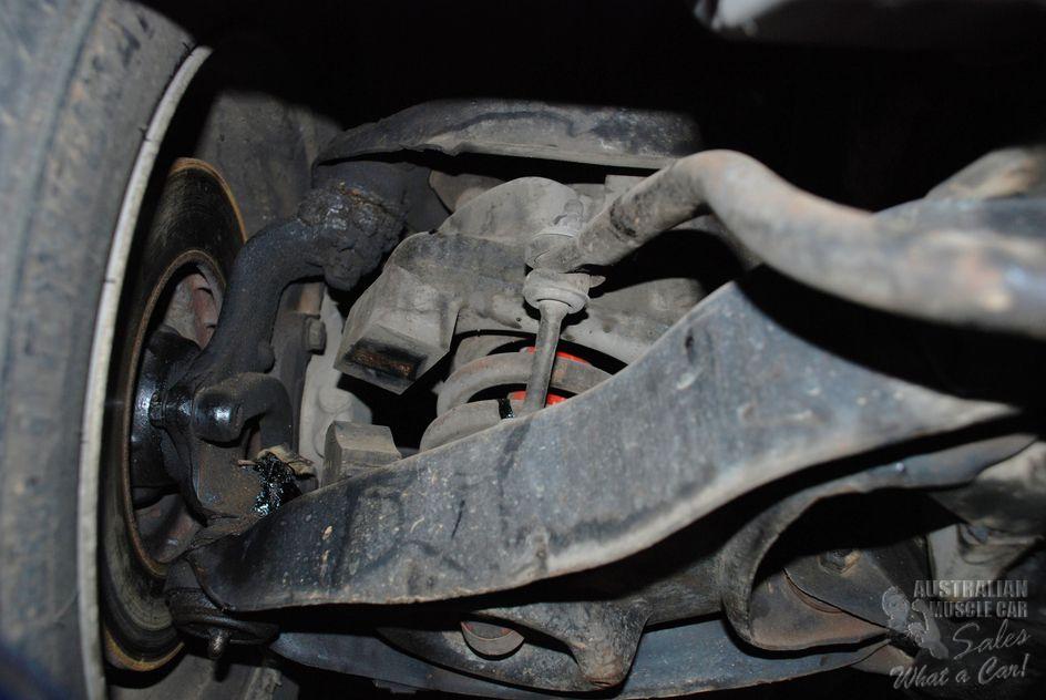
UC R/H upper arm. The ball joint is not on the centre line LH, LX are.

#5
 _martyn1960_
Posted 13 February 2011 - 10:23 AM
#6

Posted 13 February 2011 - 10:25 AM
Do you have a pic of where the holes mounting the upper control arms to the subframe are located - probably the only way to tell what you actually have but it sounds like a bit of a mix and match to me.
Edited by Toranamat69, 13 February 2011 - 10:27 AM.
#7

Posted 13 February 2011 - 01:20 PM
It is not UC as the rack has the bolt through the sub frame, not solid mount and the upper control arms are centred, not as shown.
There is no difference in the k-frame between the rubber and sold mounted steering racks. The only difference is in the steering racks.
The location of the UCA mount bolts is the main method of identifying a k-frame.
You will find some more pictures here.
http://ls2lxhatch.com/suspension.htm
#8
 _martyn1960_
Posted 13 February 2011 - 06:01 PM
#9

Posted 13 February 2011 - 06:45 PM
That page with all the front end variants is excellent - I havn't seen that before. There is a couple of things I could add for completeness if you are interrested.
Martyn1960,
I thought that pic of the UC lower arm above was yours but I see someone else actually posted that so yes, someone has done a mod to yours by the sounds of things.
After working on these front ends heaps and heaps, I finally worked out what those little rods welded to the UC subframe are for, they are to hook to top of the sub axle over to stop it drooping down under it's own weight when you have to top balljoint separated and the spring removed. They are very hand but serve no purpose when the car is up and running. I wondered for ages.
You can use those upper control arms you have and will still be able to get the standard alignment settings. There are slight advantages to using the UC offset type in that you will have a more even shim stack and the castor change through the suspension travel is less with the UC arms but the difference is tiny and probably not even noticable on a street car. If you want to wind up more castor than standard, I would chuck UC arms in. They are getting a bit exxy unless you are lucky to find a set for a good price.
The steering rack you have can be used too unless you definately want the solid mounting which is nice - both will work fine though. Some people have even replicated the A9X solid bushes to solid mount the type of rack you have there - you could do that if you didn't want to lash on a new rack and you have the tools to do it.
The UC rack uses smaller bolts for mounting so if you get a UC rack, make sure you have the metric bolts (12mm from memory) or else just run a 1/2" drill through the UC rack mounting holes which is what I did on mine.
Regarding your cracked lower control arms, plenty have been rewelded and cleaned up - nothing wrong with doing that if welded nicely. It is fairly common for them to crack.
Matt
Edited by Toranamat69, 13 February 2011 - 06:54 PM.
#10

Posted 13 February 2011 - 06:52 PM
I would be getting UC steering arms if you plan to run UC alignment specs.
Matt
#11

Posted 13 February 2011 - 09:52 PM
That page with all the front end variants is excellent - I havn't seen that before. There is a couple of things I could add for completeness if you are interrested.
Matt,
I would be happy to add any information you have to the suspension page or any other page on my website. A significant portion of the information on the suspension page has been collected from dozens of posts on this forum, including many of yours.
My theory regarding the small rod on the UC k-frame is that it was added as an extra bump stop when the UCA mount point was raised. The higher UCA mount point changes the angle of the UCA when the suspension is at full decompression which makes the rubber bump stop less effective. You can see in the photos that the UCA has contacted the rod.
Edited by ls2lxhatch, 13 February 2011 - 09:55 PM.
#12
 _martyn1960_
Posted 14 February 2011 - 06:39 AM
1 user(s) are reading this topic
0 members, 1 guests, 0 anonymous users


