12 Port Injection manifold
#26 _Inj gtr202_
Posted 10 August 2011 - 07:40 PM
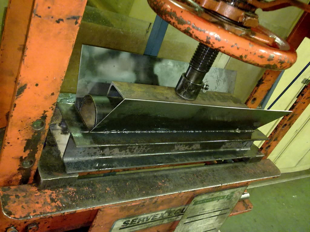
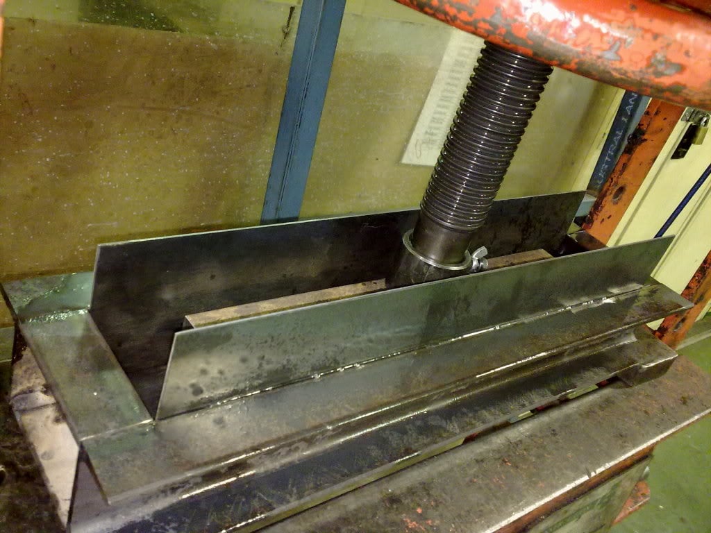
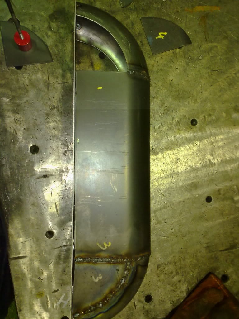
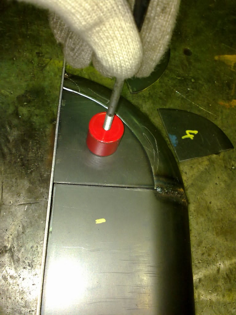
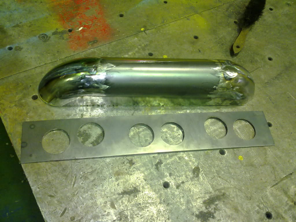
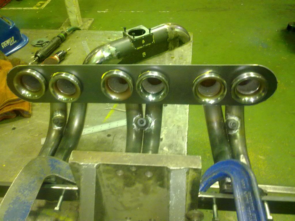
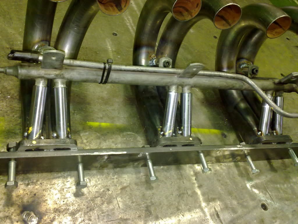
Ground the bosses flat
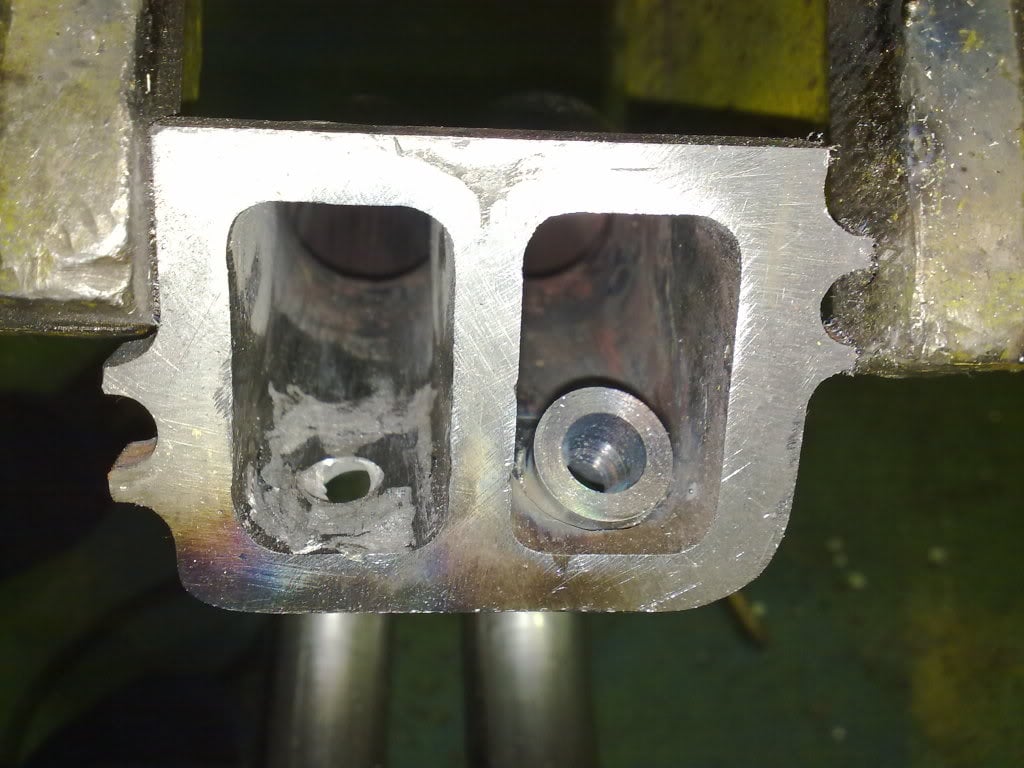
Made it look a little neater
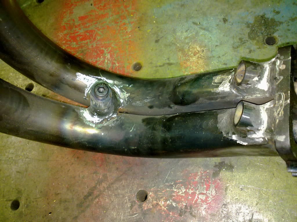
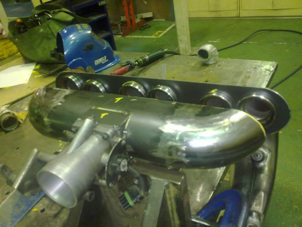
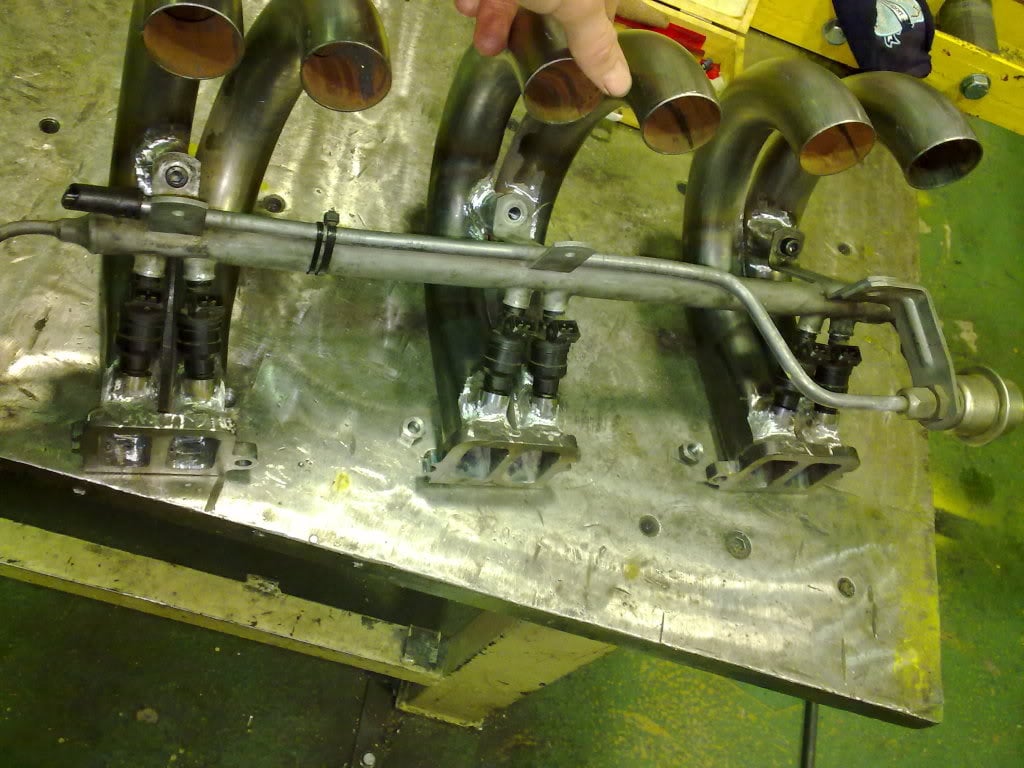
repeat 3 times and its almost ready for the plenum to be made.
#27 _Inj gtr202_
Posted 10 August 2011 - 07:43 PM
#28
Posted 11 August 2011 - 01:15 AM
#29
Posted 11 August 2011 - 08:48 AM
How did you determine the volume of the plenum?
#30 _Inj gtr202_
Posted 12 August 2011 - 12:53 AM
Can't wait to see this run.
How did you determine the volume of the plenum?
From what I have researched the volume of the plenum isn't all that critical. Its more about not feeding one runner more than the rest and not restricting the air flow.
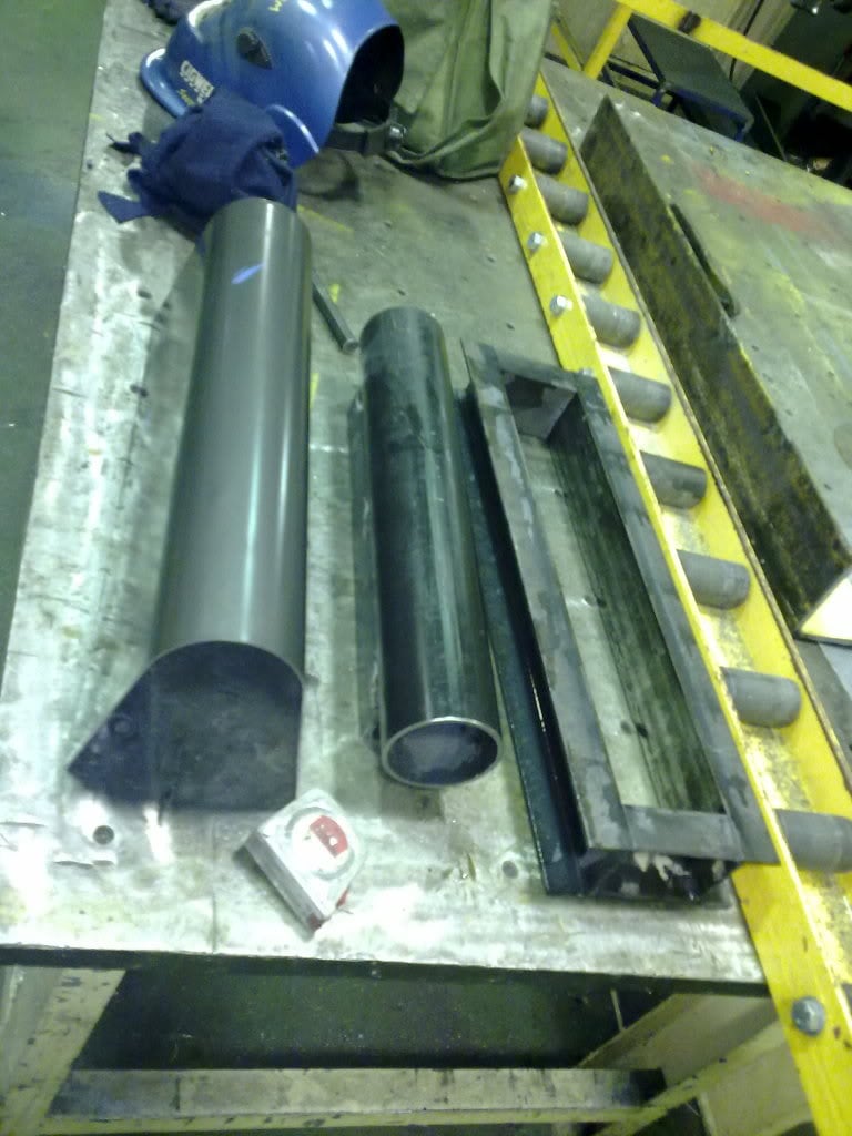
Its going to be around 500x90x100 which comes to around 4.5L. A little on the large side but due to the size of the radius at the end of each runner its as small as I can make it without impeding flow at either end.
#31
Posted 14 August 2011 - 08:57 PM
#32 _Inj gtr202_
Posted 19 August 2011 - 05:32 PM
Turns out the volume is closer to 3L rather than the the 4.5L that I predicted (tested with 600ml coke bottle)
#33 _Inj gtr202_
Posted 02 September 2011 - 05:57 PM
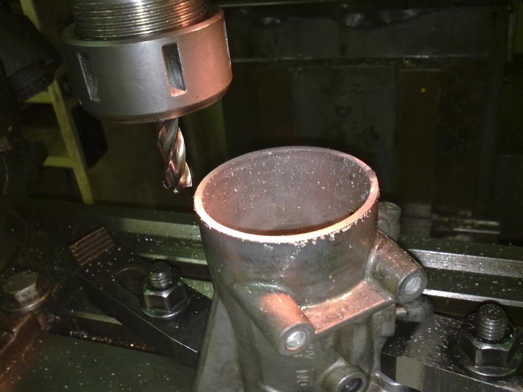
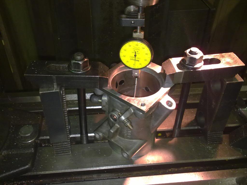
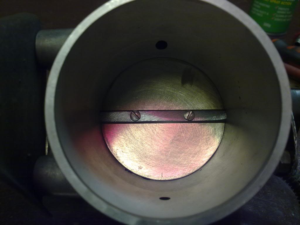
I always thought that my throttle body was 70mm. So there I was on the mill making my backing plate (for the plenum) and measured the BACK of the Throttle body.. and what do ya know.. its 65mm.
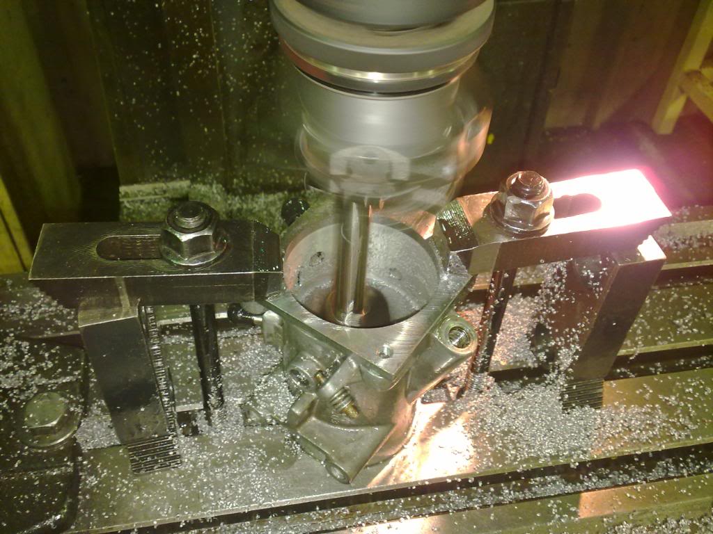
65mm may well be big enough, I don't know. So just to be sure I stripped it apart and bored it out to 70mm and made a new throttle blade.
Here are the pics.
First I sat it on the table and machined the front flat.
then flipped it over and dialed up to find center. You can see the clamps clamped on the backing plate I made to 70mm.
#34 _Inj gtr202_
Posted 02 September 2011 - 06:03 PM
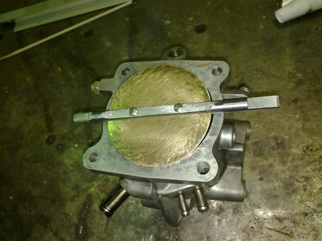
had to then flip it back over to do the front because my bore tool wouldn't go deep enough.
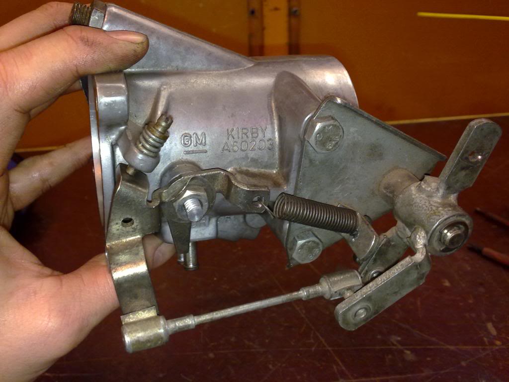
Then I turned up a new blade out of brass and filed out original throttle shaft to allow for the extra 5mm.
Decided to re-do the spring anchor point as it would have fouled on the rocker cover. That allowed me to chomp off the ugly bit which hangs down.
#35 _Inj gtr202_
Posted 02 September 2011 - 06:08 PM
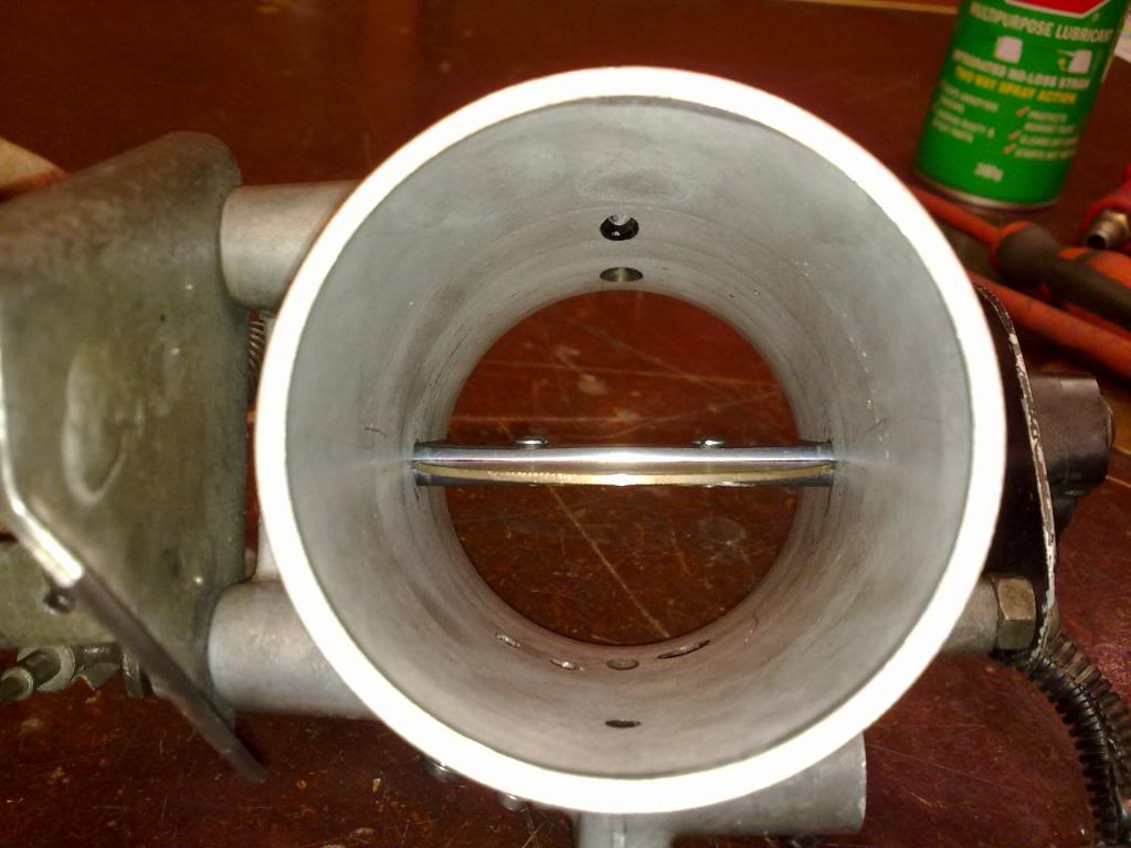
Hopefully I got it to shut tight enough not to scream at idle.
Now I am ready to give the pipes a good clean out and weld them up the Plenum.
#36 _Liam_
Posted 02 September 2011 - 06:57 PM
#37 _nicko61_
Posted 02 September 2011 - 09:39 PM
cheers Nick
#38 _Inj gtr202_
Posted 05 September 2011 - 08:19 AM
That is absolutely awesome mate... Top stuff!! How will the throttle response etc be on it you reckon?
I can only compare it to what the old one used to be like.. different cam, different head and 65mm throttle blade. I used to be pretty much perfect, just didn't have enough power.
I can't see how the extra 5mm will make that much difference to responce, the larger plenum volume will have more of an effect I would have thought.
I'm a bit worried about it all fitting under the bonnet now I sat it next to the VK manifold, Its no taller but it comes a lot further forward (towards no1 cylinder). fingers crossed
#39 _Viper_
Posted 05 September 2011 - 09:17 AM
From what ive found plenum volume should be 100% of engine compacity for N/A and 150% for engine capacity for Forced Induction
The way you have your throttle body setup id say the air will shoot straight down port 3 and 4 and you wont get as much down 1,2,5,6.
A mid entering throttle body is better but it should be facing away from the ports so it hits a wall and then disperses. You will notice most stock plenums of this kind have the ports entering from the bottom and the throttle body from the side.
It may be better to cut the runners off so they are pointing straight up and making a cylindrical plenum with dome ends and a side mounted TB
Other thing is the injectors look to be at quite a steep angle? ive found they should be no more then 20degree or aimed directly at the back of the valve as possible. I dont know how much it would effect it if they are aimed at the bottom of the ports, might cause it to pool?
Like I said im not a expert, im not trying to have a dig at what your doing just want to share what ive learnt and possibly help to make yours better in the process... What you have done does looks really good just maybe some design issues.. Id say check with a real expert and see what they think, last thing you want is to lean out the end cylinders and have it go bang. You can have a workshop flowtest it and they can tell you how much flow each runner is getting and if its even and a Decent guy will tell you what you can change to even it up.
#40 _oldjohnno_
Posted 05 September 2011 - 10:10 AM
From what ive found plenum volume should be 100% of engine compacity for N/A and 150% for engine capacity for Forced Induction
The way you have your throttle body setup id say the air will shoot straight down port 3 and 4 and you wont get as much down 1,2,5,6.
I'm no expert either but I have done a fair bit of testing of this type of manifold, checking the flow capacities and mapping velocities through each runner and the TB/plenum.
The velocity through the 70mm TB and plenum will be sufficiently low (and the pressure correspondingly high) that flow variations between runners will be negligible. And if the variation is barely measurable on the flow bench, it'll be even less so on a running engine given the amount of turbulence that will be present in the plenum. As for plenum volume I believe that 99.999% of what is written about determining the "correct" volume (whether for sizing as a hemholtz resonator or not) is horseshit. As far as I can see plenum volume is something that can only be correctly determined by dyno testing, regardless of how many formulas there are that claim to be able to do it to within 5 decimal places. Fortunately though, it seems the plenum volume is one of the least critical aspects of the manifold and so long as it isn't grossly undersized reasonable results can be expected.
Nozzle orientation doesn't seem to be critical for WOT performance, though it is important for emissions and mileage from what I can see. I don't know much at all about this though but if Brett is reading he may be able to shed some light.
#41 _Inj gtr202_
Posted 05 September 2011 - 10:44 PM
Plan B is a front mount throttle body, I was trying to avoid this because all my air ducting and throttle cables etc are set up for a tb over the rocker cover.
#42 _Inj gtr202_
Posted 27 September 2011 - 01:18 AM
Tony has the head and manifold at the moment and is going to flow test cylinders no1 and 3 or 4. He is of the same opinion as Viper, that the center 2 cylinders will get significantly more flow than the outer 4. I hope he is wrong .
I've designed up an alternative with the throttle body facing towards the radiator but really hope that the design stays as just that.... a design.
I wish I knew more about flow testing. Does the flow bench pull more or less air than the motor is capable of drawing? ie. a slight flow drop at 28" equals a massive difference at 6,500RPM or bugger all?
#43 _Viper_
Posted 27 September 2011 - 08:24 AM
Hopefully it turns out its not a problem then I wont have to worry about mine as much either
If it does turn out to be a problem can you just cut off the runners at the point where they are pointing straight up, then put your plenum on top with a side feed TB? The plenum could just be a simple cylinder with domed ends.
Edited by Viper, 27 September 2011 - 08:27 AM.
#44 _oldjohnno_
Posted 27 September 2011 - 09:56 AM
I wish I knew more about flow testing. Does the flow bench pull more or less air than the motor is capable of drawing? ie. a slight flow drop at 28" equals a massive difference at 6,500RPM or bugger all?
28" has been shown over the years to be a good compromise between being able to show a useful correlation to real-world conditions and not having to make the flowbench ridiculously big. Any reasonably sized flowbench would be able to match the real-world flow through the TB and plenum of a 202 at full noise, though some of the little ones like the baby SuperFlows would struggle.
The trouble with testing the plenum on the bench is that the flow will be smooth and continuous, whereas on the engine there will be extreme turbulence in there. That's why even if the flow bench showed some discrepancy I still wouldn't worry too much until I could get it on the dyno and check the EGTs.
#45 _ivekilledem_
Posted 27 September 2011 - 10:56 PM
#46 _Inj gtr202_
Posted 28 September 2011 - 12:44 AM
I have been planning to rebuild my 202 and get it all set up for lpg injection. I was looking at making a custom manifold for it. This is exactly what I had planned on making, with the exception on a front facing TB instead of side. I am extremely intrigued in the wedge that you have. Is this something that you have made or can it be purchased etc?
It's a block of steel I machined on a vertical milling machine.
If you don't have access to a mill an angle grinder will do the job (with patience).
or you could weld 4 pieces of round bar together to form a taper. I think Rodomo has made one in one of his build threads if you are looking for an example
The photo I posted is not the same wedge that I used (tho similar) The one I used has a much less aggressive taper and ends up at the same size as the inlet ports (which you will have to measure).
hope that makes sense
#47 _Inj gtr202_
Posted 30 September 2011 - 12:53 PM
Only no.6 cylinder was tested.
Lift " .1 .2 .3 .4 .5 .6
Head Flow 55.6 104.8 143.6 164.9 180.9 190.0
Head Flow with Manifold 53.2 97.7 129.5 147.4 161.6 166.9
% Drop 4.3 6.7 9.8 10.6 10.6 12.8
Acceptable??? .6" lift is not really relevant in this case as the cam is only .519" lift max.
#48 _oldjohnno_
Posted 30 September 2011 - 01:13 PM
To keep it in perspective it's flowing a whopping 25 - 30cfm more than the VK manifold. The potential is definitely there to make some good, yet streetable, torque and hp numbers.
Was there no test of 3 or 4?
#49 _Inj gtr202_
Posted 04 October 2011 - 12:39 PM
I don't think you're going to get much better than this without making the runner diameter excessively big.
To keep it in perspective it's flowing a whopping 25 - 30cfm more than the VK manifold. The potential is definitely there to make some good, yet streetable, torque and hp numbers.
Was there no test of 3 or 4?
no 3 or 4 couldn't be tested because the TB was in the way on his flow bench. I suggested removing the TB but he was reluctant to do so because it would have given a different result than with the TB. (plus I'm getting charged $50 a pop).
Going to drop the motor back in the next chance a I get and see how it all goes
#50 _Viper_
Posted 04 October 2011 - 01:16 PM
2 user(s) are reading this topic
0 members, 2 guests, 0 anonymous users