
Thanks Philip, So the tridon one above is not a gauge sender either?
GTR gauges LC
Started by
_glennhailstone_
, Mar 25 2012 06:50 AM
38 replies to this topic
#27
 _hutch_
_hutch_
-

- Guests
Posted 15 July 2014 - 05:31 PM
The temp sender and water temp light switch look the same,i actually have a temp sender unit here somewhere brought one put it away carefully and havnt seen the bloody thing since,so I got another one,if you go to Bursons you can get the exact VDO one out of the book
Phillip
Phillip
#28
_hutch_
_hutch_
-
- Guests
Posted 15 July 2014 - 05:35 PM
Well that's not exactly true you will need some bushes to adapt it,be careful to coz the sender unit has 1/8 bspt thread and the bush most likely will be 1/8 bspp,looking at your picture I think you bush is as I said,usually they only screw in a few turns,if you try to screw them in by force you can have sex with it
Phillip
Phillip
Edited by hutch, 15 July 2014 - 05:39 PM.
#29
_glennhailstone_
_glennhailstone_
-
- Guests
Posted 15 July 2014 - 06:30 PM
Cheers, I found one on ebay. Can you tell me why in some photos some people have two wires coming out of the oil pressure gauge sender.
Also I read somewhere that you wrap the wire around the thread before you screw it in, but there is a wire terminal on the end of the sender.
Thanks again
#30
S pack
-

- Members
-

- 15,693 posts
Scrivet Counter
- Name:Dave
- Location:Luggage Point
- Car:73 LJ
- Joined: 25-January 10
Posted 15 July 2014 - 07:18 PM
Glenn, the wire connects to the terminal on the end of the sender unit. The wire does not get wrapped around the thread before installing the sender unit.
#31
_hutch_
_hutch_
-
- Guests
Posted 15 July 2014 - 07:28 PM
Take my advice and go to Bursons,you will get the right part and if its not then you can take it back,i wont buy any thing like that off ebay
#32
_glennhailstone_
_glennhailstone_
-
- Guests
Posted 17 July 2014 - 05:24 PM
Sweet I've got the oil pressure gauge sorted thanks.
Can somebody please explain where do I take the amp gauge wire from. Also I don't know how to hook up my delco dissy, dose it just need 12V power from the battery.
Cheers
#33
_glennhailstone_
_glennhailstone_
-
- Guests
Posted 20 July 2014 - 09:10 AM
Disregard my last, about the dissy.
However more information is needed to finish off this thread and help me complete this wiring, and others of course.
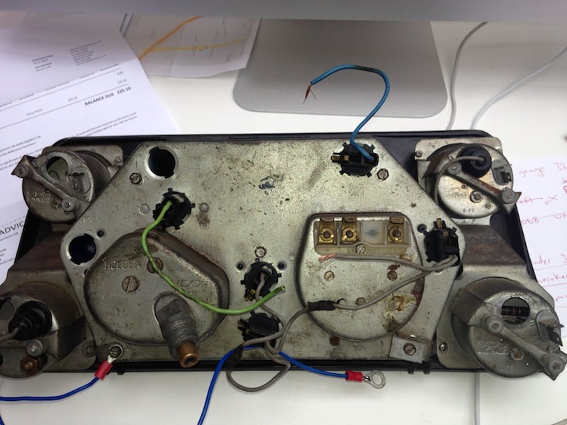
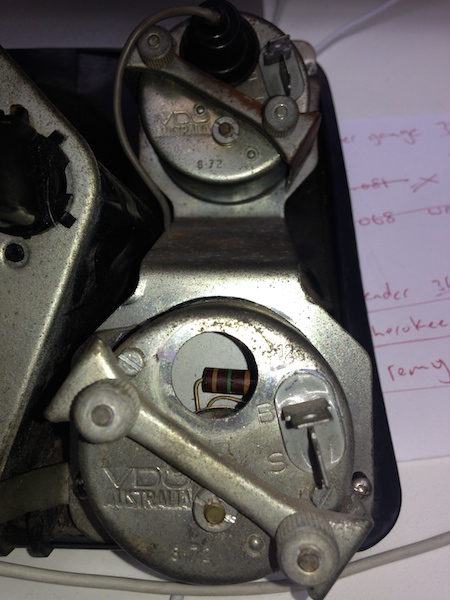
It looks like my gauges are all original VDO gauges. They have to male plugs coming out, one with S stamped next to it and the other has B stamped next to it.
I am assuming that S is for sender and B is for battery, so do I run B wire to the IGN switch. Also is there a ground wire required.
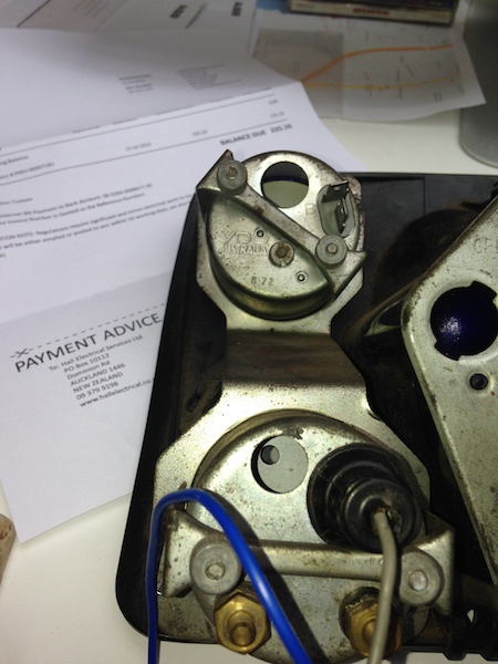
And with the GEN/AMP gauge it looks like a warning light goes in there, which I don't have. Where does this get wired up to.
Edited by glennhailstone, 20 July 2014 - 09:13 AM.
#34
_hutch_
_hutch_
-
- Guests
Posted 20 July 2014 - 02:22 PM
The ammeter needs to be connected between the battery and the all the loads and the alternator out put,it's quite a simple exercise.
To do this all you need to do is remove the alt output lead from the battery,remove the fusible link (rubbery short piece of cable) at the main terminal on the starter now connect the alt output to this lead,next you join that connection to the ammeter positive,the ammeter negative goes to the main terminal on the starter using the fusible link you removed earlier,the cable I use is a piece of 6mm twin shield cable just make sure the cable is well routed so as not to rub through,make sure you solder all the connections,the warning light light is nothing overly special,just needs to be insulated,there is a special tube that pushes into the back of the gauge,they are available on eBay at times for around $60.00 you should have a wire already there for you idiot light
To do this all you need to do is remove the alt output lead from the battery,remove the fusible link (rubbery short piece of cable) at the main terminal on the starter now connect the alt output to this lead,next you join that connection to the ammeter positive,the ammeter negative goes to the main terminal on the starter using the fusible link you removed earlier,the cable I use is a piece of 6mm twin shield cable just make sure the cable is well routed so as not to rub through,make sure you solder all the connections,the warning light light is nothing overly special,just needs to be insulated,there is a special tube that pushes into the back of the gauge,they are available on eBay at times for around $60.00 you should have a wire already there for you idiot light
#36
_glennhailstone_
_glennhailstone_
-
- Guests
Posted 21 July 2014 - 05:19 AM
Thanks very much Hutch! Do you know the part number I cant seem to find the idiot lights on ebay.
Thanks again
Edited by glennhailstone, 21 July 2014 - 05:29 AM.
#37
_hutch_
_hutch_
-
- Guests
Posted 21 July 2014 - 02:58 PM
that link is to a complete ammeter,if you try to get the globe holder out you will have sex with it.just swap it out
#38
_glennhailstone_
_glennhailstone_
-
- Guests
Posted 21 July 2014 - 05:08 PM
I only need the white warning light holder. I dont have to pull an old one out, just install a new one. Thanks for the link but that gauge looks in bad shape, and the white warning light holder is empty, no light.
I believe you can buy the warning light holder, I have seen them, I just dont know the part number.
#39
_glennhailstone_
_glennhailstone_
-
- Guests
Posted 31 July 2014 - 10:29 AM
Anyone know where I can get globe holders for the gtr dash. Thanks


1 user(s) are reading this topic
0 members, 1 guests, 0 anonymous users

