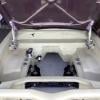
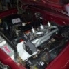
hi steve,there is more to it than just slapping that head on ,the 12 ports have extra cooling holes ,u gotta grab a 12 port gasket and lay it on the block deck and drill holes out, because of the bigger chamber it will lower compression.so a bigger cam is needed,this is a bit of a subject,cons and pros on running these heads,i think id stick to the 9 port .does anyone else concur
LJ Sedan
#101

Posted 25 November 2013 - 12:19 AM
#102

Posted 25 November 2013 - 05:31 PM
I was aware of the water jacket holes that will need to be drilled but didn't consider the bigger head chamber and change in compression. If I could use the injection manifold with a 9 port head then I'd definitely be going that way for now, much less work.
The 173 is not the motor that I plan to leave in the car, it's just the one that's in it at the moment and I figured it'd be easier to swap over the top end as opposed to changing out the whole motor for the 3.3. The 3.3 will be rebuilt while I'm working on the body for fitting up once everything is done. The other benefit to getting the 173 running with the fuel injection is that I can then use that block for the first registration meaning the PCV will be the only pollution gear required.
I put my dodgy metal fabrication skills into practice today and made up an accelerator cable bracket that mounts onto the VK fuel rail.
 1dscn1917.jpg 146.97K
12 downloads
 1dscn1924.jpg 146.53K
7 downloads
 1dscn1928.jpg 145.85K
8 downloads
It's not real pretty but it should do the job ok.
#103

Posted 02 December 2013 - 08:35 PM
Spent a solid day on the fuel tank today and got a heap of work done on fitting up the fuel pump hanger. My Chinese hole saw never showed up so paypal got my money back and another plan of attack was needed.
This is how it started off.
 1dscn1929.jpg 146.08K
7 downloads
I got this tank off Ebay a few months ago and it had been sitting open for an unknown time before then but I was still pretty wary of getting stuck into it with any kind of spark or heat. First up I thought I'd 'woof' it so I stuck it behind a big rock in the back yard and attempted to get a flame into the tank opening. Now the rock in question is about 9 foot long and 3 foot high so I had a fire stick that was about 5 foot long trying to feed a bit of flame to it. The wind kept blowing out the flame before I could get it near the tank but I did punch the hot embers on the end of the stick into the tank and got a big fat zero result. That was good enough so I drilled and cut a small opening into the side where I'd planned to hang the pump. Wish I'd done that 4 weeks ago instead of waiting for the hole saw...
Once the hole was cut I tacked the inner ring to the side of the tank initially using a big brass block as a heatsink on the inside of the tank.
 1dscn1932.jpg 141.92K
10 downloads
I ditched the heatsink after the initial tacks were completed and just finished it off doing 10mm sections at a time on different areas. I did stuff up a couple of times with a bit too much heat but it didn't turn out too bad.
 1dscn1934.jpg 145.33K
9 downloads
 1dscn1939.jpg 142.12K
11 downloads
I actually wanted to use the little TIG/Cutter to do the welding of the inner ring to the tank as I really didn't want to add a lot of material. This was especially important on the inside of the inner ring as it will house the rubber gasket for the pump hanger. Unfortunately, Ebay let me down again and the machine didn't come with any electrodes. I'd picked up some gas and filler rods the other day but didn't expect I'd need to get the electrodes as well so it was back to the MIG and a whole bunch of mess that I'd have to grind off when done. Here's the inner ring weld done in the same manner.
 1dscn1943.jpg 146.09K
8 downloads
Part 2 to of today's effort to follow.
#104

Posted 02 December 2013 - 08:52 PM
A cylindrical carbide burr with a safe edge on the end saves the day and here's the inner weld with enough space cut out for the rubber gasket. I definitely cut through the weld in a couple of areas so I think I might epoxy putty up those spots just to be sure the seal is complete. I'm also considering running a small bead of the putty around the outside weld just so it doesn't look so crappy...
 1dscn1950.jpg 147.65K
9 downloads
Next up I drilled the holes out to 9mm and fitted the sealed nutserts. I laid a little bead of epoxy tank repair around the collar of these before clamping them down just to help with the seal. I think they should be ok but I'm still undecided whether to epoxy around them on the inside of the tank and also whether they might need a small tack weld to keep them in place on the outside.
 1dscn1954.jpg 149.92K
7 downloads
Here's the final result, haven't filled it with water yet to see if it's tight. I've got a Hirsch tank sealing kit that I plan to run through it before it gets any fuel in there but I reckon it looks ok. The pump hanger is a Bosch unit out of some old Fairlane I think it was, I'd have to check the Pick and Payless receipt to be sure.
 1dscn1953.jpg 143.7K
6 downloads
The rest of the arvo was spent wire wheeling all the shit off it and then I hit it with some Phosphoric rust converter. I've never used this stuff before so I'm not sure how it goes but I'll sand it off tomorrow and hit it with an etch primer to seal it up on the outside.
 1dscn1956.jpg 144.79K
8 downloads
I did find one hole in the tank just in the upper skin barely inside the tank seam line. I'll weld that up tomorrow before priming and hopefully all will be sweet.
 1dscn1957.jpg 147.57K
7 downloads
Next up is a little in-tank swirl pot that I'll need to have a think about.
#105

Posted 03 December 2013 - 07:21 AM
Hmmm, might have stuffed up with the rust converter. I didn't immediately wipe it off the non rusted areas with a damp rag as it states in the instructions and now it's gone gummy in those areas and hasn't dried out.
Should I reapply it and then wipe it off with the damp rag to get rid of the gummy areas?
#106

Posted 03 December 2013 - 08:50 PM
Stuck it in the sun to dry out then hit it with the wire wheel again and all seems ok.
I got a coat of etch primer on it then followed it up with some matt black both from spray cans. I need to give it another topcoat tomorrow and then will get onto cleaning and sealing the inside. I'm guessing it'll be a few years before it's final fit up to the car so wanted to get it painted for now to stop any further rusting and it'll probably need refinishing at that time anyway after being fitted and removed.
 1dscn1959.jpg 141.79K
7 downloads
Still have to putty the pump gasket seal area and then give it a leak test.
#107

Posted 04 December 2013 - 10:52 AM
Nice work. At least you have the time to do it right... the first time. Dunno how many times I've had to 'go back' to something after rushing to get ready for work the next morning.
#108

Posted 04 December 2013 - 03:54 PM
good job steve ![]() tanks come up pretty neat mate,great handiwork,them nutserts are a good tool
tanks come up pretty neat mate,great handiwork,them nutserts are a good tool
#109

Posted 07 December 2013 - 08:07 PM
Cheers guys.
I think I'm going to have a go at TIG welding the inner circumference of the tank ring so I'm just waiting on some electrodes before I finish it off.
Can anyone point me to any information on the design of a small in-tank swirl pot, ie what size holes it should have around the base to ensure enough fuel gets into the pot to feed the pump but also that fuel doesn't drain from the pot too quickly. The pump I'm using is a standard VE Commodore unit and I think it pumps about 2.5 litres per minute (150lph).
#110

Posted 10 December 2013 - 09:22 PM
The TIG welding effort on the fuel tank was a complete disaster however I think I've managed to repair the damage done... Didn't get any pics but have puttied up the inner ring as I had planned earlier and will clean it up tomorrow.
Once that's done it's time to give it a leak test and if all is ok move onto the inside etch and seal. Still no idea on the swirl pot but there's plenty of time to get it sorted out.
#111

Posted 11 December 2013 - 07:45 AM
#112

Posted 11 December 2013 - 10:39 AM
Definitely new to welding in general but yeah that was my first attempt at tig welding. It seems like it could be much more accurate in the right hands but I couldn't get the setting or technique down for joining the very thin tank material to the 2mm thick ring. Just kept blowing holes in the thin stuff or couldn't get the thicker stuff to puddle. Got a couple of nice welds on the practice stuff though so I'm keen to keep going with the tig.
#113

Posted 12 December 2013 - 11:17 AM
Anyhow, the tank mods have been a bit of a failure so far...
The putty didn't really help at all in sealing up the inner ring and the leak test gave a very disappointing result. It was a slow leak but here's a couple of pics of it definitely not sealed up.
 1dscn1967.jpg 49.33K
10 downloads
 1dscn1968.jpg 145.84K
6 downloads
So the next idea is to grind out all the putty and then add material to the inner ring with the Mig to fill up the void that was to house the rubber o-ring on the pump hanger.
 1dscn1960.jpg 142.56K
5 downloads
Once this has been filled and leveled with the rest of the inner ring, I'll then cut a cork rubber gasket to use instead of the o-ring and hopefully it might just be a little more successful.
#114

Posted 13 December 2013 - 01:23 PM
So I persisted with the tig since that's the only way I'll learn how to use it and gain some experience. I do have a question though.
I'm getting some bubbling and holes left in the weld and I suspect it probably has to do with small pockets of putty that I was unable to completely remove before I started welding it up. If this is case will I be able to keep heating these areas until all the crap has been burnt off and then get a decent weld or am I just wasting my time?
 1dscn1971.jpg 135.98K
6 downloads
 1dscn1972.jpg 145.1K
6 downloads
#115

Posted 13 December 2013 - 03:55 PM
Not a tig expert... been an awful lota years, but I reckon turn the heat down a bit.
#116

Posted 13 December 2013 - 07:43 PM
Cheers Dave, I shall give that a go on the outside section to fill up a couple of seep holes I spotted earlier.
Now sorry to continue on with the boring fuel tank photos but after having very little success in burning out the impurities I decided it was time to swap to the mig and add some metal to rebuild the inner ring. Hopefully I've done enough with the tig to ensure the inner ring and tank sidewall were assimilated before I went back to the mig.
 1dscn1973.jpg 142.55K
6 downloads
The inner ring now comes all the way in to meet the fuel tank hanger with no space left over for the O-ring seal. I'll cut a cork rubber gasket that will be the same size as the inner ring and will seal against both the hanger and the outer ring to once again attempt to keep the juices inside the tank.
I don't really want to use water again to test if it seals up as it was a pain to dry out and parts had already started rusting after just an hour or so but not sure what else to use. Don't really want to fill it with petrol and then have to get rid of it...
#117

Posted 18 December 2013 - 10:01 PM
Ok more frOcking fuel tank photos so here they go.
First up I got very impatient with the welding and learnt quite a valuable lesson on metal warpage. Luckily my banana tank won't really make a difference other than losing a 10th of a litre in capacity but it's good experience.
 1dscn1974.jpg 129.68K
8 downloads
I used some putty on the inside of the nutserts this time and applied it prior to crimping them up so it would squish in and hopefully seal the holes. My ebay nutsert tool is an absolute piece of shit and will need to be replaced after crimping less than 25 nuts...
 1dscn1985.jpg 142.26K
7 downloads
Some Supercheap cork rubber was cut up to make a gasket and looks like it worked ok. I only tested it for about an hour this time with water and decided that would be good enough so it was time to get the Hirsch tank repair kit onto it.
 1dscn2012.jpg 141.57K
5 downloads
The "Miracle" cleaner/degreaser was left in the tank for about 18 hours but didn't seem to be shifting anything until I got my arm and a scrubbing brush into the tank to sort it out. In the end, with a lot of effort, it came up pretty good inside and here's a photo after the tank had been etched. Followed by a photo of the vinylester resin going off in the tank to seal it up. The instruction say that a second application of the sealer is useful if the tank had any holes so I think I will do that in a couple of days just to be sure.
 1dscn1990.jpg 135.53K
8 downloads
 1dscn2005.jpg 130.62K
5 downloads
So here it is as it stands now looking no where near as good as it did a week ago but this time being a much more functional unit.
 1dscn2011.jpg 144.09K
9 downloads
I'll swap this tank in for the original and plan to use the gauge sender unit that is in the car at the moment as I know that one works. Once I've got the injection and the in-tank pump operational I'll block off the original fuel pickup and remove the line from the boot space.
#118

Posted 19 December 2013 - 12:42 PM
Then cross that off the to do list... and start something else.
#119

Posted 21 December 2013 - 10:20 PM
Second coat of the vinylester sealer went in today and the tank is pretty much crossed off the list. I'll give it another quick squirt of paint outside to cover the parts I stuffed up with the welder and then it's ready to fit up.
I still need a little collector pot inside the tank but I think I'll make that as part of the pump hanger so it goes in and out of the tank with the pump. I also got bored after power tool hours this evening and did a quick reco on the fuel gauge sender unit that I got with the ebay tank. A little bit of electrical contact cleaner, a small piece of emery and an hour or so of scraping crap from parts saw it go from open circuit rubbish to a fully functioning 0 to 30 Ohm sender unit that I'll be more than happy to fit up.
The camera holding hand was mostly occupied with beer this arvo so this time you've all been saved the boredom of yet again, more fuel tank photos...
#120

Posted 22 December 2013 - 08:53 PM
So here's what I've come up with for a little collector pot around the pump. It'll sit about 3-4mm above the bottom of the tank and really is only meant to act as a small baffle to keep some fuel around the pickup under cornering or acceleration loads. It won't hold fuel above the general fuel level in the tank but will hopefully provide a little resistance to the fuel moving away quickly.
 1dscn2013.jpg 133.72K
8 downloads
 1dscn2014.jpg 135.68K
7 downloads
 1dscn2017.jpg 136.13K
7 downloads
I have no idea whether or not it will work or if it will even be needed seeing I'm not building an engine that will require a lot of fuel. The return line will drop fuel just above the pump strainer.
I've done a bit of research on the PVC and a number of sources indicate that it does have a useful resistance to fuel and shouldn't cause any problems in the tank. Polyethylene would probably be a better choice but this was just what I had laying around.
#121

Posted 27 December 2013 - 06:12 PM
Got the modified tank swapped in for the original today and it looks to have gone ok.
The original tank doesn't look too bad and the boot floor is mostly ok. There is a patch riveted onto the left hand side boot floor and doesn't look too good from the underside, a small rust hole around where the fuel pipe exits the boot space and another patch of rust holes on the right hand side just between the vent tube and the spare wheel bracket. The tank mounting flange looks to be in very good condition.
 1dscn2019.jpg 144.49K
10 downloads
 1dscn2030.jpg 143.28K
6 downloads
Here's the tank finally completed and ready to go in.
 1dscn2029.jpg 147.84K
8 downloads
I needed to remove just a small strip from the tank mounting flange to ensure access for the pump hanger outer ring.
 1dscn2031.jpg 140.46K
7 downloads
So it's all fitted up and I've reconnected the original pickup tube for continued use with the carby motor until I make more progress on the injection. Next step is to wire up the pump and fit the return fuel line.
Attached Files
#122

Posted 31 December 2013 - 01:38 PM
I've moved onto sorting out the wiring for the EFI setup and the first task was locating the engine computer and new fuse block. Keeping it out of view was my main priority and I had hoped to get the computer into the dash space under the radio but there just wasn't enough room for it. I'd still like to keep a radio installed in the dash so that area was ruled out.
Two other options are inside the glove box compartment or on the underside of the plenum chamber above the passenger footwell. I'd like to keep the glove box free for glove storage so attaching it to the bottom of the plenum chamber looks to be the preferred option. Can't use screws in that area so I'll make up a bracket and tack weld it on to keep the computer up and out of the way. It shouldn't be too conspicuous up there but will also be very easy to access if needed.
Next step was locating the new fuse block and relays. Again I've seen successful fuse and relay installs in the glove box area but since I am planning on removing the original fuse block I thought I might as well try getting the new one into that space under the lower dash panel. This will also save the hassle of having to extend all of the wiring from the original block.
Here's a rough knock up of the mechanism to hold the fuse block in place under the lower dash. It still requires some tweaking but appears to be functional at this stage. The fuse block was the interior part from a VZ Commodore I think and I've cut about a third of it off leaving me with around 25 fuses and 5 relay locations. More than enough to cover the original requirements and some possible future expansion.
Here it is locked in up under my spare lower dash panel.
 1dscn2085.jpg 144.04K
8 downloads
 1dscn2089.jpg 148.63K
5 downloads
A quick slide towards the front of the car and it drops out like so.
 1dscn2087.jpg 149.29K
7 downloads
It will require the headlight switch be spun around a little in it's mounting position and possibly the flasher can will need to be relocated to clear the new headlight switch cabling position. I've also moved it over a little to the left so it will no longer hit the bonnet release handle like the original fuse block had done.
 1dscn2082.jpg 140.77K
5 downloads
So a little bit of success for now though I'm yet to actually try it out in the car so it could still get thrown to the scrapheap if I find there's something in that space that I didn't notice earlier.
#123

Posted 02 January 2014 - 05:35 PM
Tried the fuse block hanger in the car yesterday and it all fit no problems, there's plenty of room up there. Once I had it in the car it became clear that there was no way I could possibly use it given that it just looked like a pile of shit. I'm surprised I even went as far as installing now that I look back at the last post. Anyhow, it did prove the concept was ok and that there was room for it but the execution was just woeful...
The test fit up showed I didn't need to slide it back into the lower dash and there was space to park it up higher to completely remove it from view. So the second iteration has been completed and I'm a lot happier with how it turned out. No sliding of sheet metal against sheet metal in this one so the movement is good and it appears to lock into the parked position fairly securely.
 1dscn2110.jpg 145.83K
7 downloads
 1dscn2115.jpg 149.23K
8 downloads
 1dscn2116.jpg 145.27K
6 downloads
I need a couple of teflon washers to go onto the pin and that should finish it off. I am a bit worried that it might rattle whilst driving but will deal with that at the time if it occurs.
A quick question on the mild steel. Do I need to sand off the light coating that it seems to have on it before I paint it or can it just be painted over after wiping down with some prepsol?
Edited by stevemc32, 02 January 2014 - 05:40 PM.
#124

Posted 09 January 2014 - 06:09 PM
Fuse block hanger got a coat of paint, some sanded down tap washers for the pin and a test fit into the car. Looks pretty good and works well. The movement is still a bit tight but I just need to do a little more sanding of the washers and that will free it up.
 1dscn2140.jpg 149.62K
8 downloads
 1dscn2142.jpg 143K
4 downloads
It's completely out of sight when latched up and now I've got the washers on it I can't see there being any problems with rattling whilst driving.
As part of the electricals I've been working on a Volkswagen relay 99 programmable intermittent wipers mod. It's taken a lot of thinking but I reckon I've finally got it sorted out, it will however require reversing the polarity of the wiper motor. Provided I keep the contact sliders in the motor well lubricated it doesn't look to be a major issue with the Preslite I have on hand but I don't think it would be as simple with the Lucas unit.
Here's some mods I've made to the wiper switch with a bit of inspiration from ribz0.
 1dscn2131.jpg 137.66K
7 downloads
The wiper switch still works as normal by twisting for High, Low and Off. The added switch is a three position with centre off, pull on for the intermittent wipers and momentary push for the washer. Just a couple more mods are required so the original section can switch the positive side of the motor and it's done.
Edited by stevemc32, 09 January 2014 - 06:12 PM.
#125

Posted 10 January 2014 - 03:08 PM
Cheers Graham.
1 user(s) are reading this topic
0 members, 1 guests, 0 anonymous users


