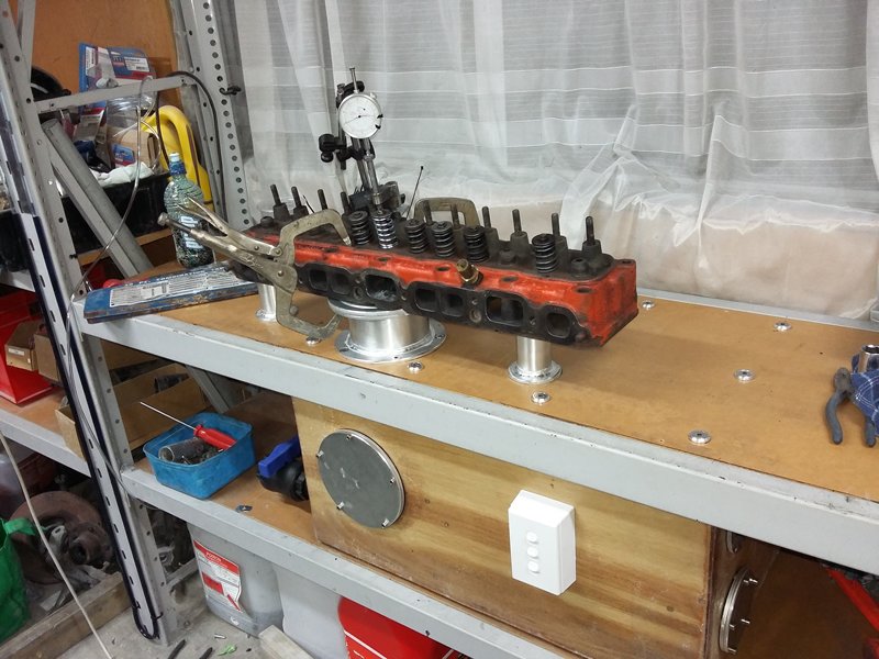
A couple guys asked about my home made Flowbench in another thread, so here are the details on how I did it.
Here is a link to the site I got my info off for the basic principle and instructions on how to make it, http://www.musclecar...r-heads-part-3/.
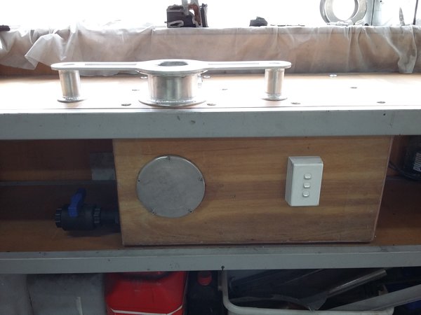
Here are some photos of the bench with a little info, if anyone wants to know anything else (After reading the link) I'll try answer your questions when I can.
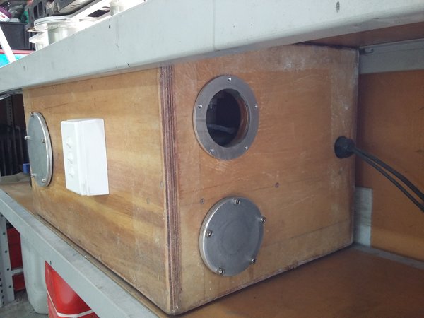
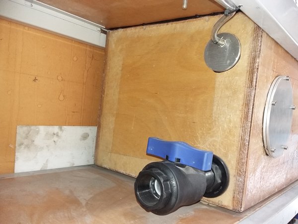
The main box is made of Plywood, and is 700L x 420W x 370H. After being screwed together, all joins were fiber glassed over and the whole box covered in resin.
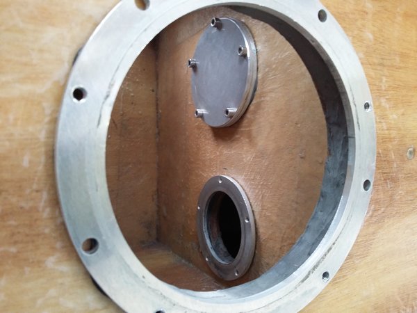
It has 3 compartments, one directly below the bore fixture (left hand side of the box looking from front) that extends to the bottom of the box, and two chambers split horizontally on the right-hand side. The top chamber on the right-hand side houses two 1100watt vacuum cleaner motors, and the inlets to the motors are sealed up around holes on the bottom shelf of the top chamber so that they are pulling from the bottom chamber.
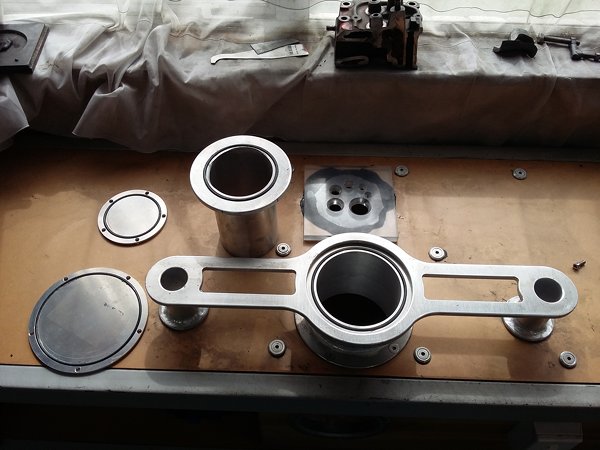
Each of the two right hand side chambers has a port that opens into the main chamber and a port to outside of the box, both of which can be blocked with o-ringed blanking plates.
When testing the inlet, the top right hand side chamber has the port into the main chamber blanked off and the port open to the outside of the box open, so the air comes into the main chamber from the head, down through the bore fixture, through the port in the lower right hand side chamber, up through the motors and out the top chambers external port.
When testing the exhaust the blanking plates are reversed so the air now enters from the outside of the box into the lower chamber, goes up through the motors and out the top right hand side chambers port into the main chamber then up through the bore fixture and head.
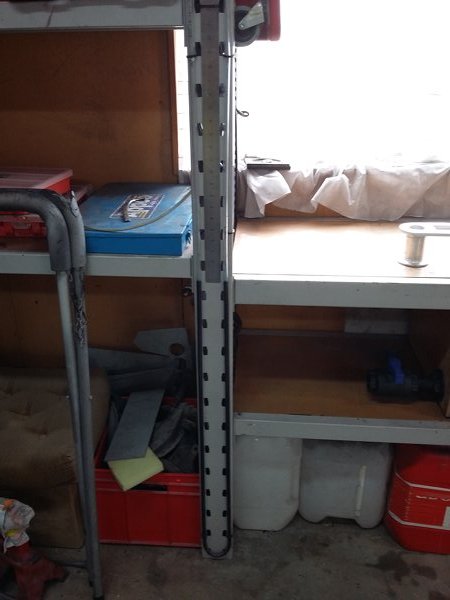
The manometer runs up and down the shelf support on the left-hand side of the bench and is plumbed to the main chamber, and reads from zero to forty inches of water.
The ball valve on the lower left hand side of the main chamber is to crack open before testing at very low cylinder head valve openings, down at 50 thou lift the vacuum can go over 40” and potentially suck all the water in the manometer through the bench, so you crack the valve, turn on the motors, wait for the water in the manometer to stabilize, then slowly close the ball valve, if it looks like it will go past 40 and the ball valve isn’t shut, you have to test at a higher valve lift.
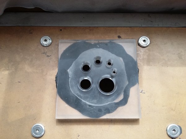
When testing, the calibration plate on the top of the bench is completely blocked up, and you open the cylinder head valve in 50 thou increment’s, noting the vacuum
readings on the manometer at each stage.
These readings are then compared to the readings previously taken off the calibration plate. The holes in the calibration plate are sized for 5, 10, 20, 40, 80, and 160 cfm and by blocking and unblocking the holes in sequence and noting the reading on the manometer you get readings from 5 to 315 cfm in 5 cfm increments.
Because I don’t have any sort of voltage regulation yet, the vacuum the motors pull can vary depending on how much electrical load you have on in the rest of the house/garage, so after I test the head I will usually close the valve in the head and check the calibration plate tests the same as my reference readings, if not you can adjust the figures up or down as needed.


